Intel BLKDG43NB Product Specification - Page 56
Thermal Considerations - warranty
 |
UPC - 735858201773
View all Intel BLKDG43NB manuals
Add to My Manuals
Save this manual to your list of manuals |
Page 56 highlights
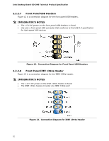
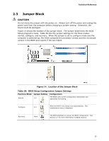
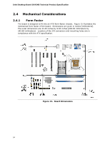
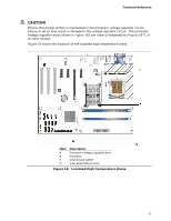
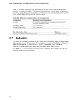
Intel Desktop Board DG43NB Technical Product Specification 2.5.2 Fan Header Current Capability CAUTION The processor fan must be connected to the processor fan header, not to a chassis fan header. Connecting the processor fan to a chassis fan header may result in onboard component damage that will halt fan operation. Table 30 lists the current capability of the fan headers. Table 30. Fan Header Current Capability Fan Header Maximum Available Current Processor fan Front chassis fan Rear chassis fan Auxiliary chassis fan 2.0 A 1.5 A 1.5 A 2.0 A 2.5.3 Add-in Board Considerations The board is designed to provide 2 A (average) of +5 V current for each add-in board. The total +5 V current draw for add-in boards for a fully loaded board (all three expansion slots filled and the PCI Express x16 connector filled) must not exceed 8 A. 2.6 Thermal Considerations CAUTION Failure to ensure appropriate airflow may result in reduced performance of both the processor and/or voltage regulator or, in some instances, damage to the board. For a list of chassis that have been tested with Intel desktop boards please refer to the following website: http://developer.intel.com/design/motherbd/cooling.htm All responsibility for determining the adequacy of any thermal or system design remains solely with the reader. Intel makes no warranties or representations that merely following the instructions presented in this document will result in a system with adequate thermal performance. CAUTION Ensure that the ambient temperature does not exceed the board's maximum operating temperature. Failure to do so could cause components to exceed their maximum case temperature and malfunction. For information about the maximum operating temperature, see the environmental specifications in Section 2.8. 56
-
 1
1 -
2
-
3
-
4
-
5
-
6
-
7
-
8
-
9
-
10
-
11
-
12
-
13
-
14
-
15
-
16
-
17
-
18
-
19
-
20
-
21
-
22
-
23
-
24
-
25
-
26
-
27
-
28
-
29
-
30
-
31
-
32
-
33
-
34
-
35
-
36
-
37
-
38
-
39
-
40
-
41
-
42
-
43
-
44
-
45
-
46
-
47
-
48
-
49
-
50
-
 51
51 -
 52
52 -
 53
53 -
 54
54 -
 55
55 -
 56
56 -
 57
57 -
 58
58 -
 59
59 -
 60
60 -
 61
61 -
62
-
63
-
64
-
65
-
66
-
67
-
68
-
69
-
70
-
71
-
72
-
73
-
74
-
75
-
76
-
77
-
78
-
79
-
80
-
81
-
82
-
83
-
84
-
85
-
86
-
87
-
88
 |
 |