Intel BOXD865PCDL Product Specification
Intel BOXD865PCDL - P4 PGA478 865P MATX DDR333 Manual
 |
UPC - 735858167413
View all Intel BOXD865PCDL manuals
Add to My Manuals
Save this manual to your list of manuals |
Intel BOXD865PCDL manual content summary:
- Intel BOXD865PCDL | Product Specification - Page 1
® Desktop Board D865PCD Technical Product Specification April 2004 Order Number: C73314-001 The Intel® Desktop Board D865PCD may contain design defects or errors known as errata that may cause the product to deviate from published specifications. Current characterized errata - Intel BOXD865PCDL | Product Specification - Page 2
or characteristics of any features or instructions marked "reserved" or "undefined." Intel reserves these for future definition and 1793-421-333, other Countries 708-296-9333. Intel, Pentium, and Celeron are registered trademarks of Intel Corporation or its subsidiaries in the United States and other - Intel BOXD865PCDL | Product Specification - Page 3
power and environmental requirements, and the BIOS for the Intel® Desktop Board D865PCD. It describes the standard product and the Desktop Board D865PCD A map of the resources of the Desktop Board The features supported by the BIOS Setup program The contents of the BIOS Setup program's menus and - Intel BOXD865PCDL | Product Specification - Page 4
Intel Desktop Board D865PCD Technical Product Specification WARNING Warnings indicate conditions, which if not observed, can cause personal injury. Other Common Notation # (NxnX) GB GB/sec - Intel BOXD865PCDL | Product Specification - Page 5
1.1.1 Feature Summary 12 1.1.2 Board Layout 13 1.1.3 Block Diagram 14 1.2 Online Support ...15 1.3 Design Specifications 16 1.4 Processor ...19 1.5 System Memory ...20 1.5.1 Memory Configurations 22 1.6 Intel® 865P Chipset ...24 1.6.1 Universal 0.8 V / 1.5 V AGP 3.0 Connector 24 1.6.2 USB...25 - Intel BOXD865PCDL | Product Specification - Page 6
3.6.1 Language Support 72 3.6.2 Custom Splash Screen 73 3.7 Recovering BIOS Data 73 3.8 Boot Options...74 3.8.1 CD-ROM Boot 74 3.8.2 Network Boot 74 3.8.3 Booting Without Attached Devices 74 3.8.4 Changing the Default Boot Device During POST 74 3.9 Fast Booting Systems with Intel® Rapid BIOS - Intel BOXD865PCDL | Product Specification - Page 7
Contents 4 BIOS Setup Program 4.1 Introduction...77 4.2 Maintenance Menu ...78 4.3 Main Menu...79 4.4 Advanced Menu...80 4.4.1 PCI Configuration Submenu 81 4.4.2 Boot Configuration Submenu 82 4.4.3 Peripheral Configuration Submenu 83 4.4.4 Drive Configuration Submenu 85 4.4.5 Floppy - Intel BOXD865PCDL | Product Specification - Page 8
Intel Desktop Board D865PCD ...16 3. Supported System Bus Frequency and Memory Speed Combinations 20 4. Supported Memory Configurations 21 18. Rear Chassis Fan Connector 49 19. ATX12V Power Connector 49 20. Processor Fan Connector 49 21. Main Power Connector 49 22. Front Chassis Fan Connector - Intel BOXD865PCDL | Product Specification - Page 9
Contents 26. States for a One-Color Power LED 54 27. States for a Two-Color Power LED 54 28. Front Panel Audio Connector/Jumper Block 57 29. BIOS Setup Configuration Jumper Settings 57 30. DC Loading Characteristics 60 31. Fan Connector Current Capability 60 32. Thermal Considerations for - Intel BOXD865PCDL | Product Specification - Page 10
Intel Desktop Board D865PCD Technical Product Specification x - Intel BOXD865PCDL | Product Specification - Page 11
1 Product Description What This Chapter Contains 1.1 Overview ...12 1.2 Online Support ...15 1.3 Design Specifications 16 1.4 Processor ...19 1.5 System Memory ...20 1.6 Intel® 865P Chipset ...24 1.7 I/O Controller ...27 1.8 Audio Subsystem...28 1.9 LAN Subsystem...29 1.10 Chassis Intrusion and - Intel BOXD865PCDL | Product Specification - Page 12
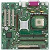
microATX (9.60 inches by 9.60 inches [243.84 millimeters by 243.84 millimeters]) Processor • Support for an Intel® Pentium® 4 processor in an mPGA478 socket with a 400 or 533 MHz system bus • Support for an Intel® Celeron® processor in an mPGA478 socket with a 400 MHz system bus Memory • Two 184 - Intel BOXD865PCDL | Product Specification - Page 13
device (optional) D AGP connector E Rear chassis fan connector F Back panel connectors G +12V power connector (ATX12V) H mPGA478 processor socket I Processor fan connector J Intel 82865P MCH K DIMM Channel A socket L DIMM Channel B socket M I/O controller N Power connector OM17040 O Diskette drive - Intel BOXD865PCDL | Product Specification - Page 14
IDE Interface mPGA478 Processor Socket System Bus (400/533 MHz) USB LPC Bus I/O Controller LPC Bus Back Panel/ Front Panel USB Ports Serial Port Parallel Port PS/2 Mouse PS/2 Keyboard Diskette Drive Connector AGP Interface Universal 0.8/ 1.5 V AGP 3.0 Connector Intel 82865P Memory Controller - Intel BOXD865PCDL | Product Specification - Page 15
Board D865PCD Processor data sheets ICH5 addressing Custom splash screens Audio software and utilities LAN software and drivers Visit this World Wide Web site: http://www.intel.com/design/motherbd http://support.intel.com/support/motherboards/desktop http://developer.intel.com/design/motherbd - Intel BOXD865PCDL | Product Specification - Page 16
Chair, Seagate Technology. ATX ATX Specification Version 2.03, December 1998, Intel Corporation. ATX12V ATX/ATX12V Power Supply Design Guide Version 1.2, August 2000, Intel Corporation. BIS Boot Integrity Services (BIS) Version 1.0, Application Programming August 4, 1999, Interface (API - Intel BOXD865PCDL | Product Specification - Page 17
Interface Specification microATX Motherboard Interface Specification PCI 1994, Compaq Computer Corporation, Phoenix Technologies Limited, and Intel Corporation. The information is specs-cdrom.pdf http://www.intel.com/design /chipsets/industry/lpc.htm http://www.formfactors.org/ developer/specs - Intel BOXD865PCDL | Product Specification - Page 18
WfM Wired for Management Baseline Version 2.0, December 18, 1998, Intel Corporation. The information is available from... ftp://download.intel.com/lab s/manage/wfm/download/p xespec.pdf http://www.formfactors.org/ developer/specs/sfx/sfx12v. pdf http://www.dmtf.org/downlo ad/standards/DSP0119 - Intel BOXD865PCDL | Product Specification - Page 19
when using an Intel Pentium 4 processor operating above 2.80 GHz with this Intel® desktop board. The board is designed to support the following: • Intel Pentium 4 processors in an mPGA478 processor socket with a 400 or 533 MHz system bus • Intel Celeron processors in an mPGA478 processor socket with - Intel BOXD865PCDL | Product Specification - Page 20
Intel Desktop Board D865PCD Technical Product Specification 1.5 System Memory The board has two DIMM sockets and supports supported system bus frequency and memory speed combinations. Table 3. Supported System Bus Frequency and Memory Speed Combinations To use this type of DIMM... The processor - Intel BOXD865PCDL | Product Specification - Page 21
Product Description Table 4 lists the supported DIMM configurations. Table 4. Supported Memory Configurations DIMM Capacity DDR SDRAM Configuration Density DDR SDRAM Organization Number of DDR Front-side/Back-side SDRAM Devices 64 MB SS 64 Mbit 8 M x 8/ - Intel BOXD865PCDL | Product Specification - Page 22
Desktop Board D865PCD Technical Product Specification 1.5.1 Memory Configurations The Intel 82865P MCH component provides two features for enhancing memory throughput: • Dual Channel memory interface. The board has two memory channels, each with a single DIMM socket, - Intel BOXD865PCDL | Product Specification - Page 23
Figure 4. Example of Dual Channel Configuration with Dynamic Mode Single Channel Configuration with Dynamic Mode (Single DIMM) Channel A DIMM Intel 82865P MCH Channel B DIMM Throughput Level Highest Configuration Dual Channel with Dynamic Mode Single Channel with Dynamic Mode Single Channel - Intel BOXD865PCDL | Product Specification - Page 24
FWH provides the nonvolatile storage of the BIOS. For information about The Intel 865P chipset Resources used by the chipset Refer to http://developer.intel.com/ Chapter 2 1.6.1 Universal 0.8 V / 1.5 V AGP 3.0 Connector The AGP connector supports the following: • 4x, 8x AGP 3.0 add-in cards with - Intel BOXD865PCDL | Product Specification - Page 25
requirements for full-speed devices. • Native USB 2.0 support has been tested with drivers for Windows* 2000 (with Service Pack 3) and Windows XP (with Service Pack 1) and is not currently supported by any other operating system. Check Intel's Desktop Board website for possible driver updates for - Intel BOXD865PCDL | Product Specification - Page 26
Intel Desktop Board D865PCD Technical Product Specification 1.6.3 IDE Support The board provides two Parallel ATA IDE connectors, which support support the following modes: • Programmed I/O (PIO): processor controls data transfer. • 8237-style DMA: DMA offloads the processor, supporting transfer - Intel BOXD865PCDL | Product Specification - Page 27
port connector Setting the parallel port's mode Refer to Figure 8, page 44 Table 46, page 83 1.7.3 Diskette Drive Controller The I/O controller supports one diskette drive. Use the BIOS Setup program to configure the diskette drive interface. For information about The location of the diskette - Intel BOXD865PCDL | Product Specification - Page 28
Intel Desktop Board D865PCD Technical Product Specification 1.7.4 Keyboard and Mouse Interface PS/2 keyboard and mouse connectors are located on the back panel. ✏ NOTE The keyboard is supported in the bottom PS/2 connector and the mouse is supported in the top PS/2 connector. Power to the computer - Intel BOXD865PCDL | Product Specification - Page 29
include: • PCI bus master interface • CSMA/CD protocol engine • PCI power management Supports ACPI technology Supports LAN wake capabilities 1.9.1 Intel® 82562EZ Physical Layer Interface Device The Intel 82562EZ provides the following functions: • Basic 10/100 Ethernet LAN connectivity • Full - Intel BOXD865PCDL | Product Specification - Page 30
selected 1.9.3 LAN Subsystem Software LAN software and drivers are available from Intel's World Wide Web site. For information about Obtaining LAN software and 15 1.10 Chassis Intrusion and Detection The Desktop Board D865PCD supports a chassis security feature that detects if the chassis cover is - Intel BOXD865PCDL | Product Specification - Page 31
Plug and Play functions of a computer. The use of ACPI with the Desktop Board D865PCD requires an operating system that provides full ACPI support. ACPI features include: • Plug and Play (including bus and device enumeration) • Power management control of individual devices, add-in boards (some add - Intel BOXD865PCDL | Product Specification - Page 32
Intel Desktop Board D865PCD Technical Product Specification Table 8. Power States and Targeted System Power Global States G0 - working state G1 - sleeping state G1 - sleeping state G1 - sleeping state G2/S5 Sleeping States S0 - working S1 - Processor to the system. Service can be performed safely - Intel BOXD865PCDL | Product Specification - Page 33
✏ NOTE The use of Resume on Ring and Wake from USB technologies from an ACPI state requires an operating system that provides full ACPI support. 1.11.2.1 Power Connector ATX12V-, SFX12V-, and TFX12V-compliant power supplies can turn off the system power through system control. When an ACPI-enabled - Intel BOXD865PCDL | Product Specification - Page 34
Intel Desktop Board D865PCD Technical Product Specification For information about The a wake-up signal that powers up the computer. Depending on the LAN implementation, the Desktop Board D865PCD support LAN wake capabilities with ACPI in the following ways: • The PCI bus PME# signal for PCI 2.2 - Intel BOXD865PCDL | Product Specification - Page 35
states. ✏ NOTE Wake from USB requires the use of a USB peripheral that supports Wake from USB. 1.11.2.6 Wake from PS/2 Devices PS/2 device activity wakes from an ACPI S1 or S3 state. 1.11.2.7 PME# Signal Wake-up Support When the PME# signal on the PCI bus is asserted, the computer wakes from - Intel BOXD865PCDL | Product Specification - Page 36
Intel Desktop Board D865PCD Technical Product Specification 36 - Intel BOXD865PCDL | Product Specification - Page 37
2 Technical Reference What This Chapter Contains 2.1 Introduction...37 2.2 Memory Map ...37 2.3 DMA Channels ...38 2.4 Fixed I/O Map...38 2.5 PCI Configuration Space Map 39 2.6 Interrupts ...40 2.7 PCI Interrupt Routing Map 41 2.8 Connectors ...43 2.9 Jumper Blocks...56 2.10 Mechanical - Intel BOXD865PCDL | Product Specification - Page 38
03E8 - 03EF 03F0 - 03F5 03F4 - 03F7 7 bits 8 bytes 12 bytes 32 bytes 8 bytes 6 bytes 1 byte Secondary IDE channel status port LPT1 Intel 82865P MCH Intel 82865P MCH COM3 Diskette channel Primary Parallel ATA IDE channel control block 03F8 - 03FF 8 bytes COM1 04D0 - 04D1 2 bytes Edge/level - Intel BOXD865PCDL | Product Specification - Page 39
01 03 1E Function Number (hex) 00 00 00 00 Description Memory controller of Intel 82865P component Host to AGP bridge (virtual PCI-to-PCI) PCI to CSA Bridge (virtual PCI-to-PCI) Hub link to PCI bridge 00 1F 00 Intel 82801EB ICH5 PCI to LPC bridge 00 1F 01 Parallel ATA IDE controller 00 - Intel BOXD865PCDL | Product Specification - Page 40
Intel Desktop Board D865PCD Technical Product Specification 2.6 Interrupts The interrupts can be routed through either the Programmable Interrupt Controller (PIC) or the Advanced Programmable Interrupt Controller (APIC) portion of the ICH5 component. The PIC is supported in Windows 98 SE and - Intel BOXD865PCDL | Product Specification - Page 41
Technical Reference 2.7 PCI Interrupt Routing Map This section describes interrupt sharing and how the interrupt signals are connected between the PCI bus connectors and onboard PCI devices. The PCI specification specifies how interrupts can be shared between devices attached to the PCI bus. In most - Intel BOXD865PCDL | Product Specification - Page 42
Intel Desktop Board D865PCD Technical Product Specification Table 15. PCI Interrupt Routing Map PCI Interrupt Source PIRQA AGP connector INTA ICH5 USB UHCI controller 1 INTA SMBus - Intel BOXD865PCDL | Product Specification - Page 43
Technical Reference 2.8 Connectors CAUTION Only the following connectors have overcurrent protection: back panel USB, front panel USB, and PS/2. The other internal connectors are not overcurrent protected and should connect only to devices inside the computer's chassis, such as fans and internal - Intel BOXD865PCDL | Product Specification - Page 44
Intel Desktop Board D865PCD Technical Product Specification 2.8.1 Back Panel Connectors Figure 8 shows the location of the back panel connectors. The back panel connectors are color-coded - Intel BOXD865PCDL | Product Specification - Page 45
connector 2 only (ATX expansion slot 6). PCI add-in cards with SMBus support can access sensor data and other information residing on the Desktop Board. ✏ NOTE This document references back-panel slot numbering with respect to processor location on the board. The AGP slot is not numbered. PCI slots - Intel BOXD865PCDL | Product Specification - Page 46
Intel Desktop Board D865PCD Technical Product Specification 2.8.2.2 Audio Connectors Figure 9 shows the location of the audio connectors. A B 12 9 10 1 4 Item A B Description ATAPI CD-ROM (black) Front - Intel BOXD865PCDL | Product Specification - Page 47
Technical Reference Table 16. ATAPI CD-ROM Connector Pin Signal Name 1 Left audio input from CD-ROM 2 CD audio differential ground 3 CD audio differential ground 4 Right audio input from CD-ROM Table 17. Front Panel Audio Connector Pin Signal Name Pin 1 Mono Mic in (Stereo Mic 1) 2 - Intel BOXD865PCDL | Product Specification - Page 48
Intel Desktop Board D865PCD Technical Product Specification 2.8.2.3 Power and Hardware Control D C Item A B C D E F Description Rear chassis fan +12 V power connector (ATX12V) Processor fan Main power Front chassis fan Chassis intrusion For more information see: Table 18 Table 19 Table 20 Table - Intel BOXD865PCDL | Product Specification - Page 49
with the Desktop Board D865PCD. ATX12V, SFX12V, and TFX12V power supplies have an additional power lead that provides required supplemental power for the processor. Always connect the 20-pin and 4-pin leads of ATX12V, SFX12V, and TFX12V power supplies to the corresponding connectors on the desktop - Intel BOXD865PCDL | Product Specification - Page 50
Intel Desktop Board D865PCD Technical Product Specification Table 22. Front Chassis Fan Connector Pin Signal Name 1 Control 2 +12 V 3 Tach Table 23. Chassis Intrusion Connector Pin Signal Name 1 Intruder 2 Ground 50 - Intel BOXD865PCDL | Product Specification - Page 51
the PCI bus connectors are bus master capable. • SMBus signals are routed to PCI bus connector 2. This enables PCI bus add-in boards with SMBus support to access sensor data on the Desktop Board. The specific SMBus signals are as follows: The SMBus clock line is connected to pin A40. The - Intel BOXD865PCDL | Product Specification - Page 52
Intel Desktop Board D865PCD Technical Product Specification # INTEGRATOR'S NOTES • The AGP connector used in PCI bus connectors 1 and 2 (the PCI bus connectors closest to the processor). To avoid clearance problems, install PCI video cards in PCI bus connector 3. 2.8.3 External I/O Connectors Figure - Intel BOXD865PCDL | Product Specification - Page 53
Technical Reference 2.8.3.1 Auxiliary Front Panel Power/Sleep/Message-Waiting LED Connector Pins 1 and 3 of this connector duplicate the signals on pins 2 and 4 of the front panel connector. Table 24. Auxiliary Front Panel Power/Sleep/Message-Waiting LED Connector Pin Signal Name 1 - Intel BOXD865PCDL | Product Specification - Page 54
Intel Desktop Board D865PCD Technical Product Specification 2.8.3.2.1 Hard Drive Activity LED Connector Pins 1 and 3 can be connected to an LED to provide a visual indicator that data - Intel BOXD865PCDL | Product Specification - Page 55
Technical Reference 2.8.3.3 Front Panel USB Connectors Figure 14 is a connection diagram for the front panel USB connector. # INTEGRATOR'S NOTES • The +5 V DC power on the USB connector is fused. • Pins 1, 3, 5, and 7 comprise one USB port. • Pins 2, 4, 6, and 8 comprise one USB port. • Use only a - Intel BOXD865PCDL | Product Specification - Page 56
Intel Desktop Board D865PCD Technical Product Specification 2.9 Jumper Blocks CAUTION Do not move any jumpers with the power on. Always turn off the power and unplug - Intel BOXD865PCDL | Product Specification - Page 57
other than the one described in Table 28. Other jumper configurations are not supported and could damage the Desktop Board. Table 28. Front Panel Audio Connector/Jumper and the computer is powered-up, the BIOS compares the processor version and the microcode version in the BIOS and reports - Intel BOXD865PCDL | Product Specification - Page 58
Intel Desktop Board D865PCD Technical Product Specification 2.10 Mechanical Considerations 2.10.1 Form Factor The Desktop Board D865PCD is designed to fit into either a microATX or an - Intel BOXD865PCDL | Product Specification - Page 59
specification. ✏ NOTE The I/O shield drawings in this document are for reference only. An I/O shield compliant with the ATX chassis specification 2.03 is available from Intel. 0.884 [22.450] 0.276 [7.012] 0.00 0.465 [11.811] 0.567 [14.400] 6.390 Ref [162.300] 0.787±0.010 TYP [20±0.254] 0.039 Dia - Intel BOXD865PCDL | Product Specification - Page 60
Intel Desktop Board D865PCD Technical Product Specification 2.11 Electrical Considerations with a 500 mA current draw per USB port. These calculations are not based on specific processor values or memory configurations but are based on the minimum and maximum current draw possible from the - Intel BOXD865PCDL | Product Specification - Page 61
of standby current required depends on the wake devices supported and manufacturing options. System integrators should refer to of an Intel Pentium 4 processor operating above 2.80 GHz with this Intel desktop board Intel makes no warranties or representations that merely following the instructions - Intel BOXD865PCDL | Product Specification - Page 62
reach a temperature of up to 85 oC in an open chassis. Figure 18 shows the locations of the localized high temperature zones. A B C D Item A B C D Description Processor voltage regulator area Processor Intel 82865P MCH Intel 82801EB ICH5 OM17041 Figure 18. Localized High Temperature Zones 62 - Intel BOXD865PCDL | Product Specification - Page 63
the Desktop Board D865PCD. Table 32. Thermal Considerations for Components Component Intel Pentium 4 processor Intel 82865P MCH Intel 82801EB ICH5 Maximum Case Temperature For processor case temperature, see processor datasheets and processor specification updates 99 oC (under bias) 115 oC (under - Intel BOXD865PCDL | Product Specification - Page 64
Intel Desktop Board D865PCD Technical Product Specification 2.14 Environmental Table 33 lists the environmental specifications for the Desktop Board D865PCD. Table 33. Desktop Board D865PCD Environmental - Intel BOXD865PCDL | Product Specification - Page 65
Technical Reference 2.15 Regulatory Compliance This section describes the Desktop Boards' compliance with U.S. and international safety and electromagnetic compatibility (EMC) regulations. 2.15.1 Safety Regulations Table 34 lists the safety regulations the Desktop Board D865PCD complies with when - Intel BOXD865PCDL | Product Specification - Page 66
energy and, if not installed and used in accordance with the instructions, may cause harmful interference to radio communications. However, there is Any changes or modifications to the equipment not expressly approved by Intel Corporation could void the user's authority to operate the equipment. 2.15 - Intel BOXD865PCDL | Product Specification - Page 67
component side). The CE mark should also be on the shipping container. Australian Communications Authority (ACA) C-Tick mark. Includes adjacent Intel supplier code number, N-232. The C-tick mark should also be on the shipping container. Printed wiring board manufacturer's recognition mark: consists - Intel BOXD865PCDL | Product Specification - Page 68
Intel Desktop Board D865PCD Technical Product Specification 68 - Intel BOXD865PCDL | Product Specification - Page 69
69 3.3 Resource Configuration 70 3.4 System Management BIOS (SMBIOS 71 3.5 Legacy USB Support 71 3.6 BIOS Updates ...72 3.7 Recovering BIOS Data 73 3.8 Boot Options...74 3.9 Fast Booting Systems with Intel® Rapid BIOS Boot 75 3.10 BIOS Security Features 76 3.1 Introduction The Desktop - Intel BOXD865PCDL | Product Specification - Page 70
Intel up the two PCI IDE connectors with independent I/O channel support. The IDE interface supports hard drives up to ATA-66/100 and recognizes of the drive. You can override the auto-configuration options by specifying manual configuration in the BIOS Setup program. To use ATA-66/100 features the - Intel BOXD865PCDL | Product Specification - Page 71
asset tags • Resource data, such as memory size, cache size, and processor speed • Dynamic data, such as event detection and error logging Non-Plug information. The BIOS supports an SMBIOS table interface for such operating systems. Using this support, an SMBIOS service-level application running - Intel BOXD865PCDL | Product Specification - Page 72
Web. • Intel® Flash Memory Update Utility, which requires creation of a boot diskette and manual rebooting of instructions distributed with the upgrade utility before attempting a BIOS update. For information about The Intel World Wide Web site Refer to Section 1.2, page 15 3.6.1 Language Support - Intel BOXD865PCDL | Product Specification - Page 73
diskette, a bootable diskette must be created and the BIOS update files copied to it. BIOS upgrades and the Intel Flash Memory Update Utility are available from Intel Customer Support through the Intel World Wide Web site. ✏ NOTE Even if the computer is configured to boot from an LS-120 diskette - Intel BOXD865PCDL | Product Specification - Page 74
Intel Desktop Board D865PCD Technical Product Specification 3.8 Boot Options In the BIOS ATAPI CD-ROM third. The fourth device is disabled. 3.8.1 CD-ROM Boot Booting from CD-ROM is supported in compliance to the El Torito bootable CD-ROM format specification. Under the Boot menu in the BIOS Setup - Intel BOXD865PCDL | Product Specification - Page 75
of option ROM boot time. ✏ NOTE It is possible to optimize the boot process to the point where the system boots so quickly that the Intel logo screen (or a custom logo splash screen) will not be seen. Monitors and hard disk drives with minimum initialization times can also contribute to a boot - Intel BOXD865PCDL | Product Specification - Page 76
Intel Desktop Board D865PCD Technical Product Specification 3.10 BIOS Security Features The BIOS includes security features that restrict access to the BIOS Setup program and who - Intel BOXD865PCDL | Product Specification - Page 77
menu features. Table 39. BIOS Setup Program Menu Bar Maintenance Main Advanced Security Clears passwords and displays processor information Displays processor and memory configuration Configures advanced features available through the chipset Sets passwords and security features Power Boot - Intel BOXD865PCDL | Product Specification - Page 78
Intel Desktop Board D865PCD Technical Product Specification Table 40 lists the function keys Security Power Boot Exit The menu shown in Table 41 is for clearing Setup passwords and displaying processor information. Setup only displays this menu in configure mode. See Section 2.9.2 on page 57 for - Intel BOXD865PCDL | Product Specification - Page 79
type. Disables/enables Hyper-Threading Technology. This option is present only when a processor that supports Hyper-Threading Technology is installed. Displays processor speed. Displays the system bus speed. Displays the system memory speed. Displays the size of second-level cache. Displays - Intel BOXD865PCDL | Product Specification - Page 80
Intel Desktop Board D865PCD Technical Product Specification 4.4 Advanced Menu To access this menu, select Advanced on the of connected IDE devices. Configures the diskette drive. Configures Event Logging. Configures video features. Configures USB support. Configures advanced chipset features. 80 - Intel BOXD865PCDL | Product Specification - Page 81
BIOS Setup Program 4.4.1 PCI Configuration Submenu To access this submenu, select Advanced on the menu bar and then PCI Configuration. Maintenance Main Advanced Security Power PCI Configuration Boot Configuration Peripheral Configuration Drive Configuration Floppy Configuration Event Log - Intel BOXD865PCDL | Product Specification - Page 82
Intel Desktop Board D865PCD Technical Product Specification 4.4.2 Boot Configuration Configuration Submenu Feature Options Description Plug & Play O/S • No (default) • Yes Specifies if manual configuration is desired. No lets the BIOS configure all devices. This setting is appropriate when - Intel BOXD865PCDL | Product Specification - Page 83
BIOS Setup Program 4.4.3 Peripheral Configuration Submenu To access this submenu, select Advanced on the menu bar and then Peripheral Configuration. Maintenance Main Advanced Security Power PCI Configuration Boot Configuration Peripheral Configuration Drive Configuration Floppy Configuration - Intel BOXD865PCDL | Product Specification - Page 84
Intel Desktop Board D865PCD Technical Product Specification Table 46. Peripheral (This feature is present only when Parallel Port Mode is set to ECP) Audio Onboard LAN ASF Support Options Description • Disabled Configures the parallel port. • Enabled Auto assigns LPT1 the address 378h and - Intel BOXD865PCDL | Product Specification - Page 85
Description Enables/disables the use of DMA for hard drive BIOS INT13 reads and writes. Specifies the hard disk drive pre-delay. Not supported Not supported Reports type of connected device on Parallel ATA (PATA) IDE primary master interface. Reports type of connected device on Parallel ATA (PATA - Intel BOXD865PCDL | Product Specification - Page 86
Intel Desktop Board D865PCD Technical Product Specification 4.4.4.1 PATA Submenus To access these submenus, the PATA IDE submenus. For brevity, only one example is shown. ✏ NOTE SATA support is not present on the Desktop Board D865PCD. The SATA submenus in this BIOS screen are not accessible. 86 - Intel BOXD865PCDL | Product Specification - Page 87
BIOS Setup Program Table 48. PATA Submenus Feature Drive Installed Type Maximum Capacity LBA/Large Mode Block Mode PIO Mode DMA Mode S.M.A.R.T. Cable Detected Options No options • Auto (default) • User No options • Disabled • Auto (default) • Disabled • Auto (default) Auto (default) 0 1 2 3 4 • - Intel BOXD865PCDL | Product Specification - Page 88
Intel Desktop Board D865PCD Technical Product Specification 4.4.5 Floppy Configuration Submenu To access this menu, select Advanced on the menu bar and then Floppy Configuration. Maintenance Main - Intel BOXD865PCDL | Product Specification - Page 89
BIOS Setup Program 4.4.6 Event Log Configuration Submenu To access this menu, select Advanced on the menu bar and then Event Log Configuration. Maintenance Main Advanced Security Power PCI Configuration Boot Configuration Peripheral Configuration Drive Configuration Floppy Configuration Event - Intel BOXD865PCDL | Product Specification - Page 90
Intel Desktop Board D865PCD Technical Product Specification 4.4.7 Video Configuration Submenu To access this menu, select Advanced on the menu bar and then Video Configuration. Maintenance Main - Intel BOXD865PCDL | Product Specification - Page 91
USB features. Table 52. USB Configuration Submenu Feature Options High-Speed USB • Enabled (default) • Disabled Legacy USB Support • Disabled • Enabled (default) USB 2.0 Legacy Support • Full-Speed (default) • Hi-Speed Description Set to Disabled when a USB 2.0 driver is not available - Intel BOXD865PCDL | Product Specification - Page 92
Intel Desktop Board D865PCD Technical Product Specification 4.4.9 Chipset Configuration Submenu To access this menu, select Advanced on the menu bar and then Chipset Configuration. Maintenance Main - Intel BOXD865PCDL | Product Specification - Page 93
to the memory detected. Manual - Aggressive = Selects most aggressive user-defined timings. Manual - User Defined = Allows manual override of detected SDRAM Defined. 2. This option is displayed only if the installed processor has a 533 MHz system bus. 3. This feature is displayed only if SDRAM Timing - Intel BOXD865PCDL | Product Specification - Page 94
Intel Desktop Board D865PCD Technical Product Specification 4.5 Security Menu To access this menu, select Security from the menu bar at the top of the screen. Maintenance - Intel BOXD865PCDL | Product Specification - Page 95
S5 • Stay Off (default) • Power On Description S1 is the safest mode but consumes more power. S3 consumes less power, but some drivers may not support this state. In ACPI soft-off mode only, determines how the system responds to a LAN wake-up event. 95 - Intel BOXD865PCDL | Product Specification - Page 96
the computer to boot without running certain POST tests. Disables/enables PXE boot to LAN. Note: When set to Enabled, you must reboot for the Intel Boot Agent device to be available in the Boot Device menu. Disables/enables booting to USB boot devices. Specifies the boot sequence from the available - Intel BOXD865PCDL | Product Specification - Page 97
Priority Submenu Feature 1st Boot Device 2nd Boot Device 3rd Boot Device 4th Boot Device Options • Removable Dev. • Hard Drive • ATAPI CD-ROM • Intel® Boot Agent (Note) • Disabled Description Specifies the boot sequence according to the device type. The computer will attempt to boot from up to - Intel BOXD865PCDL | Product Specification - Page 98
Intel Desktop Board D865PCD Technical Product Specification 4.7.2 Hard Disk Drives Submenu To . This list will display up to twelve hard disk drives, the maximum number of hard disk drives supported by the BIOS. 4.7.3 Removable Devices Submenu To access this menu, select Boot on the menu bar, - Intel BOXD865PCDL | Product Specification - Page 99
device of this type is installed. This list will display up to four ATAPI CD-ROM drives, the maximum number of ATAPI CD-ROM drives supported by the BIOS. 4.8 Exit Menu To access this menu, select Exit from the menu bar at the top of the screen. Maintenance Main Advanced Security - Intel BOXD865PCDL | Product Specification - Page 100
Intel Desktop Board D865PCD Technical Product Specification 100 - Intel BOXD865PCDL | Product Specification - Page 101
5 Error Messages and Beep Codes What This Chapter Contains 5.1 BIOS Error Messages 101 5.2 Port 80h POST Codes 103 5.3 Bus Initialization Checkpoints 107 5.4 Speaker ...108 5.5 BIOS Beep Codes ...108 5.1 BIOS Error Messages Table 63 lists the error messages and provides a brief description of - Intel BOXD865PCDL | Product Specification - Page 102
Intel Desktop Board D865PCD Technical Product Specification Table 63. BIOS Error Messages Size Increased Memory size has increased since the last boot. If no memory was added there may be a problem with the system. Memory Size Changed Memory size has changed since the last boot. If no memory was - Intel BOXD865PCDL | Product Specification - Page 103
recovery code in F000 Shadow RAM. Initialize interrupt vector tables, initialize system timer, initialize DMA controller and interrupt controller. Initialize extra (Intel Recovery) Module. Initialize floppy drive. Try to boot from floppy. If reading of boot sector is successful, give control to boot - Intel BOXD865PCDL | Product Specification - Page 104
Intel Desktop Board D865PCD Technical Product Specification Table 66. Runtime Code Uncompressed in F000 Shadow RAM Code 03 05 06 07 08 0B 0C 0E 0F - Intel BOXD865PCDL | Product Specification - Page 105
Error Messages and Beep Codes Table 66. Runtime Code Uncompressed in F000 Shadow RAM (continued) Code 40 42 43 44 45 46 47 48 49 4B 4C 4D 4E 4F 50 51 52 53 54 57 58 59 60 62 65 66 7F 80 81 82 83 Description of POST Operation To prepare the descriptor tables. To enter in virtual mode for memory - Intel BOXD865PCDL | Product Specification - Page 106
Intel Desktop Board D865PCD Technical Product Specification Table 66. Runtime Code Uncompressed in F000 Shadow the system configuration. Put INT13 module runtime image to shadow. Generate MP for multiprocessor support (if present). Put CGA INT10 module (if present) in Shadow. continued 106 - Intel BOXD865PCDL | Product Specification - Page 107
Error Messages and Beep Codes Table 66. Runtime Code Uncompressed in F000 Shadow RAM (continued) Code AE B1 00 Description of POST Operation Uncompress SMBIOS module and init SMBIOS code and form the runtime SMBIOS image in shadow. Going to copy any code to specific area. Copying of code to - Intel BOXD865PCDL | Product Specification - Page 108
Intel Desktop Board D865PCD Technical Product Specification Table 69 describes the BIOS Beep Codes Whenever a recoverable error occurs during POST, the BIOS displays an error message describing the problem (see Table 70). The BIOS also issues a beep code (one long tone followed by two short tones - Intel BOXD865PCDL | Product Specification - Page 109
Error Messages and Beep Codes If POST completes normally, the BIOS issues one short beep before passing control to the operating system. Table 70. Beep Codes Beep Description 1 Memory error 3 Memory error 6 System failure 7 System failure 8 Video error 109 - Intel BOXD865PCDL | Product Specification - Page 110
Intel Desktop Board D865PCD Technical Product Specification 110
-
 1
1 -
 2
2 -
 3
3 -
 4
4 -
 5
5 -
 6
6 -
 7
7 -
8
-
9
-
10
-
11
-
12
-
13
-
14
-
15
-
16
-
17
-
18
-
19
-
20
-
21
-
22
-
23
-
24
-
25
-
26
-
27
-
28
-
29
-
30
-
31
-
32
-
33
-
34
-
35
-
36
-
37
-
38
-
39
-
40
-
41
-
42
-
43
-
44
-
45
-
46
-
47
-
48
-
49
-
50
-
51
-
52
-
53
-
54
-
55
-
56
-
57
-
58
-
59
-
60
-
61
-
62
-
63
-
64
-
65
-
66
-
67
-
68
-
69
-
70
-
71
-
72
-
73
-
74
-
75
-
76
-
77
-
78
-
79
-
80
-
81
-
82
-
83
-
84
-
85
-
86
-
87
-
88
-
89
-
90
-
91
-
92
-
93
-
94
-
95
-
96
-
97
-
98
-
99
-
100
-
101
-
102
-
103
-
104
-
105
-
106
-
107
-
108
-
109
-
110
 |
 |

April 2004
Order Number:
C73314-001
The Intel
®
Desktop Board D865PCD may contain design defects or errors known as errata that may cause the product to deviate from published specifications.
Current
characterized errata are documented in the Intel Desktop Board D865PCD Specification Update.
Intel
®
Desktop Board
D865PCD
Technical Product Specification