Intel BOXD865PCDL Product Specification - Page 8

s, Tables

Page 8 highlights

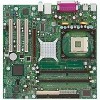
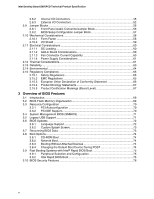
Intel Desktop Board D865PCD Technical Product Specification Figures 1. Desktop Board D865PCD Components 13 2. Block Diagram ...14 3. Memory Channel Configuration 22 4. Example of Dual Channel Configuration with Dynamic Mode 23 5. Example of Single Channel Configuration with Dynamic Mode 23 6. Example of Single Channel Configuration without Dynamic Mode 24 7. LAN Connector LED Locations 30 8. Back Panel Connectors 44 9. Audio Connectors ...46 10. Power and Hardware Control Connectors 48 11. D865PCD Add-in Board and Peripheral Interface Connectors 51 12. External I/O Connectors 52 13. Connection Diagram for Front Panel Connector 53 14. Connection Diagram for Front Panel USB Connector 55 15. Location of the Jumper Blocks 56 16. Desktop Board D865PCD Dimensions 58 17. I/O Shield Dimensions 59 18. Localized High Temperature Zones 62 Tables 1. Feature Summary...12 2. Specifications ...16 3. Supported System Bus Frequency and Memory Speed Combinations 20 4. Supported Memory Configurations 21 5. Characteristics of Dual/Single Channel Configuration with/without Dynamic Mode.....22 6. LAN Connector LED States 30 7. Effects of Pressing the Power Switch 31 8. Power States and Targeted System Power 32 9. Wake-up Devices and Events 32 10. System Memory Map 37 11. DMA Channels ...38 12. I/O Map ...38 13. PCI Configuration Space Map 39 14. Interrupts ...40 15. PCI Interrupt Routing Map 42 16. ATAPI CD-ROM Connector 47 17. Front Panel Audio Connector 47 18. Rear Chassis Fan Connector 49 19. ATX12V Power Connector 49 20. Processor Fan Connector 49 21. Main Power Connector 49 22. Front Chassis Fan Connector 50 23. Chassis Intrusion Connector 50 24. Auxiliary Front Panel Power/Sleep/Message-Waiting LED Connector 53 25. Front Panel Connector 53 viii

  • 1
  • 2
  • 3
  • 4
  • 5
  • 6
  • 7
  • 8
  • 9
  • 10
  • 11
  • 12
  • 13
  • 14
  • 15
  • 16
  • 17
  • 18
  • 19
  • 20
  • 21
  • 22
  • 23
  • 24
  • 25
  • 26
  • 27
  • 28
  • 29
  • 30
  • 31
  • 32
  • 33
  • 34
  • 35
  • 36
  • 37
  • 38
  • 39
  • 40
  • 41
  • 42
  • 43
  • 44
  • 45
  • 46
  • 47
  • 48
  • 49
  • 50
  • 51
  • 52
  • 53
  • 54
  • 55
  • 56
  • 57
  • 58
  • 59
  • 60
  • 61
  • 62
  • 63
  • 64
  • 65
  • 66
  • 67
  • 68
  • 69
  • 70
  • 71
  • 72
  • 73
  • 74
  • 75
  • 76
  • 77
  • 78
  • 79
  • 80
  • 81
  • 82
  • 83
  • 84
  • 85
  • 86
  • 87
  • 88
  • 89
  • 90
  • 91
  • 92
  • 93
  • 94
  • 95
  • 96
  • 97
  • 98
  • 99
  • 100
  • 101
  • 102
  • 103
  • 104
  • 105
  • 106
  • 107
  • 108
  • 109
  • 110

Intel Desktop Board D865PCD Technical Product Specification
viii
Figures
1.
Desktop Board D865PCD Components
......................................................................
13
2.
Block Diagram
............................................................................................................
14
3.
Memory Channel Configuration
..................................................................................
22
4.
Example of Dual Channel Configuration with Dynamic Mode
.....................................
23
5.
Example of Single Channel Configuration with Dynamic Mode
...................................
23
6.
Example of Single Channel Configuration without Dynamic Mode
.............................
24
7.
LAN Connector LED Locations
...................................................................................
30
8.
Back Panel Connectors
..............................................................................................
44
9.
Audio Connectors
.......................................................................................................
46
10.
Power and Hardware Control Connectors
..................................................................
48
11.
D865PCD Add-in Board and Peripheral Interface Connectors
....................................
51
12.
External I/O Connectors
.............................................................................................
52
13.
Connection Diagram for Front Panel Connector
.........................................................
53
14.
Connection Diagram for Front Panel USB Connector
.................................................
55
15.
Location of the Jumper Blocks
....................................................................................
56
16.
Desktop Board D865PCD Dimensions
.......................................................................
58
17.
I/O Shield Dimensions
................................................................................................
59
18.
Localized High Temperature Zones
............................................................................
62
Tables
1.
Feature Summary
.......................................................................................................
12
2.
Specifications
.............................................................................................................
16
3.
Supported System Bus Frequency and Memory Speed Combinations
.......................
20
4.
Supported Memory Configurations
.............................................................................
21
5.
Characteristics of Dual/Single Channel Configuration with/without Dynamic Mode
.....
22
6.
LAN Connector LED States
........................................................................................
30
7.
Effects of Pressing the Power Switch
.........................................................................
31
8.
Power States and Targeted System Power
................................................................
32
9.
Wake-up Devices and Events
.....................................................................................
32
10.
System Memory Map
..................................................................................................
37
11.
DMA Channels
...........................................................................................................
38
12.
I/O Map
......................................................................................................................
38
13.
PCI Configuration Space Map
....................................................................................
39
14.
Interrupts
....................................................................................................................
40
15.
PCI Interrupt Routing Map
..........................................................................................
42
16.
ATAPI CD-ROM Connector
........................................................................................
47
17.
Front Panel Audio Connector
.....................................................................................
47
18.
Rear Chassis Fan Connector
.....................................................................................
49
19.
ATX12V Power Connector
..........................................................................................
49
20.
Processor Fan Connector
...........................................................................................
49
21.
Main Power Connector
...............................................................................................
49
22.
Front Chassis Fan Connector
.....................................................................................
50
23.
Chassis Intrusion Connector
.......................................................................................
50
24.
Auxiliary Front Panel Power/Sleep/Message-Waiting LED Connector
........................
53
25.
Front Panel Connector
...............................................................................................
53