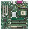
Intel BOXD865PCDL Product Specification - Page 39
PCI Configuration Space Map
 |
UPC - 735858167413
View all Intel BOXD865PCDL manuals
Add to My Manuals
Save this manual to your list of manuals |
Page 39 highlights
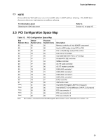
Technical Reference ✏ NOTE Some additional I/O addresses are not available due to ICH5 address aliasing. The ICH5 data sheet provides more information on address aliasing. For information about Obtaining the ICH5 data sheet Refer to Section 1.2 on page 15 2.5 PCI Configuration Space Map Table 13. PCI Configuration Space Map Bus Number (hex) 00 00 00 00 Device Number (hex) 00 01 03 1E Function Number (hex) 00 00 00 00 Description Memory controller of Intel 82865P component Host to AGP bridge (virtual PCI-to-PCI) PCI to CSA Bridge (virtual PCI-to-PCI) Hub link to PCI bridge 00 1F 00 Intel 82801EB ICH5 PCI to LPC bridge 00 1F 01 Parallel ATA IDE controller 00 1F 03 SMBus controller 00 1F 05 AC '97 audio controller 00 1F 06 AC '97 modem controller 00 1D 00 USB UHCI controller 1 00 1D 01 USB UHCI controller 2 00 1D 02 USB UHCI controller 3 00 1D 03 USB UHCI controller 4 00 1D 07 EHCI controller 01 00 00 AGP add-in card (Note) 01 00 Intel 82547EI Gigabit LAN PLC (if present) (Note) 08 00 Intel 82562EZ 10/100 Mbits/sec LAN PLC (if present) (Note) 00 00 PCI bus connector 1 (Note) 01 00 PCI bus connector 2 (Note) 02 00 PCI bus connector 3 Note: Bus number = 03 when the Intel 82547EI Gigabit LAN controller is used. Otherwise, bus number = 02. 39
-
 1
1 -
2
-
3
-
4
-
5
-
6
-
7
-
8
-
9
-
10
-
11
-
12
-
13
-
14
-
15
-
16
-
17
-
18
-
19
-
20
-
21
-
22
-
23
-
24
-
25
-
26
-
27
-
28
-
29
-
30
-
31
-
32
-
33
-
 34
34 -
 35
35 -
 36
36 -
 37
37 -
 38
38 -
 39
39 -
 40
40 -
 41
41 -
 42
42 -
 43
43 -
 44
44 -
45
-
46
-
47
-
48
-
49
-
50
-
51
-
52
-
53
-
54
-
55
-
56
-
57
-
58
-
59
-
60
-
61
-
62
-
63
-
64
-
65
-
66
-
67
-
68
-
69
-
70
-
71
-
72
-
73
-
74
-
75
-
76
-
77
-
78
-
79
-
80
-
81
-
82
-
83
-
84
-
85
-
86
-
87
-
88
-
89
-
90
-
91
-
92
-
93
-
94
-
95
-
96
-
97
-
98
-
99
-
100
-
101
-
102
-
103
-
104
-
105
-
106
-
107
-
108
-
109
-
110
 |
 |
