Intel BOXD865PCDL Product Specification - Page 45
Internal I/O Connectors
 |
UPC - 735858167413
View all Intel BOXD865PCDL manuals
Add to My Manuals
Save this manual to your list of manuals |
Page 45 highlights
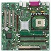
Technical Reference 2.8.2 Internal I/O Connectors The internal I/O connectors are divided into the following functional groups: • Audio (see page 46) ATAPI CD-ROM Front panel audio • Power and hardware control (see page 48) Fans [3] ATX12V power Main power Chassis intrusion • Add-in boards and peripheral interfaces (see page 51) PCI bus AGP IDE Diskette drive 2.8.2.1 Expansion Slots The board has the following expansion slots: • AGP connector: The AGP connector is keyed for Universal 0.8 V AGP 3.0 cards or 1.5 V AGP 2.0 cards only. Do not install a legacy 3.3 V AGP card. The AGP connector is not mechanically compatible with legacy 3.3 V AGP cards. • Three PCI rev 2.2 compliant local bus slots. The SMBus is routed to PCI bus connector 2 only (ATX expansion slot 6). PCI add-in cards with SMBus support can access sensor data and other information residing on the Desktop Board. ✏ NOTE This document references back-panel slot numbering with respect to processor location on the board. The AGP slot is not numbered. PCI slots are identified as PCI slot #x, starting with the slot closest to the processor. Figure 11 (page 51) illustrates the board's PCI slot numbering. 45
-
 1
1 -
2
-
3
-
4
-
5
-
6
-
7
-
8
-
9
-
10
-
11
-
12
-
13
-
14
-
15
-
16
-
17
-
18
-
19
-
20
-
21
-
22
-
23
-
24
-
25
-
26
-
27
-
28
-
29
-
30
-
31
-
32
-
33
-
34
-
35
-
36
-
37
-
38
-
39
-
 40
40 -
 41
41 -
 42
42 -
 43
43 -
 44
44 -
 45
45 -
 46
46 -
 47
47 -
 48
48 -
 49
49 -
 50
50 -
51
-
52
-
53
-
54
-
55
-
56
-
57
-
58
-
59
-
60
-
61
-
62
-
63
-
64
-
65
-
66
-
67
-
68
-
69
-
70
-
71
-
72
-
73
-
74
-
75
-
76
-
77
-
78
-
79
-
80
-
81
-
82
-
83
-
84
-
85
-
86
-
87
-
88
-
89
-
90
-
91
-
92
-
93
-
94
-
95
-
96
-
97
-
98
-
99
-
100
-
101
-
102
-
103
-
104
-
105
-
106
-
107
-
108
-
109
-
110
 |
 |
