Intel BOXD865PERL Product Specification - Page 37
Audio Connectors
 |
UPC - 735858160056
View all Intel BOXD865PERL manuals
Add to My Manuals
Save this manual to your list of manuals |
Page 37 highlights
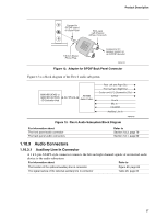
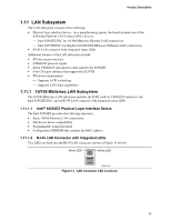
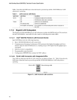
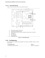
Product Description Connect to S/PDIF output on Back Panel RCA Jack Left Channel (White, if colored) 1/8-inch Stereo Phone Plug Connect to 5.1 speaker system or an S/PDIF decoder OM16108 Figure 12. Adapter for S/PDIF Back Panel Connector Figure 13 is a block diagram of the Flex 6 audio subsystem. 82801EB (ICH5) or 82801ER (ICH5-R) I/O Controller Hub AC '97 Link AD1985 Audio Codec Rear Left and Right Out Front Left and Right Out Center and LFE (Subwoofer) Out S/PDIF Line In Mic In CD-ROM Auxiliary Line In Figure 13. Flex 6 Audio Subsystem Block Diagram OM16105 For information about The front panel audio connector The back panel audio connectors Refer to Section 2.8.3, page 70 Section 2.8.1, page 60 1.10.3 Audio Connectors 1.10.3.1 Auxiliary Line In Connector A 1 x 4-pin ATAPI-style connector connects the left and right channel signals of an internal audio device to the audio subsystem. For information about Refer to The location of the optional auxiliary line in connector Figure 20, page 63 The signal names of the optional auxiliary line in connector Table 26, page 64 37
-
 1
1 -
2
-
3
-
4
-
5
-
6
-
7
-
8
-
9
-
10
-
11
-
12
-
13
-
14
-
15
-
16
-
17
-
18
-
19
-
20
-
21
-
22
-
23
-
24
-
25
-
26
-
27
-
28
-
29
-
30
-
31
-
 32
32 -
 33
33 -
 34
34 -
 35
35 -
 36
36 -
 37
37 -
 38
38 -
 39
39 -
 40
40 -
 41
41 -
 42
42 -
43
-
44
-
45
-
46
-
47
-
48
-
49
-
50
-
51
-
52
-
53
-
54
-
55
-
56
-
57
-
58
-
59
-
60
-
61
-
62
-
63
-
64
-
65
-
66
-
67
-
68
-
69
-
70
-
71
-
72
-
73
-
74
-
75
-
76
-
77
-
78
-
79
-
80
-
81
-
82
-
83
-
84
-
85
-
86
-
87
-
88
-
89
-
90
-
91
-
92
-
93
-
94
-
95
-
96
-
97
-
98
-
99
-
100
-
101
-
102
-
103
-
104
-
105
-
106
-
107
-
108
-
109
-
110
-
111
-
112
-
113
-
114
-
115
-
116
-
117
-
118
-
119
-
120
-
121
-
122
-
123
-
124
-
125
-
126
-
127
-
128
-
129
-
130
-
131
-
132
 |
 |
