Intel BOXD865PERL Product Specification - Page 72
Front Panel USB Connectors, INTEGRATOR, S NOTES
 |
UPC - 735858160056
View all Intel BOXD865PERL manuals
Add to My Manuals
Save this manual to your list of manuals |
Page 72 highlights
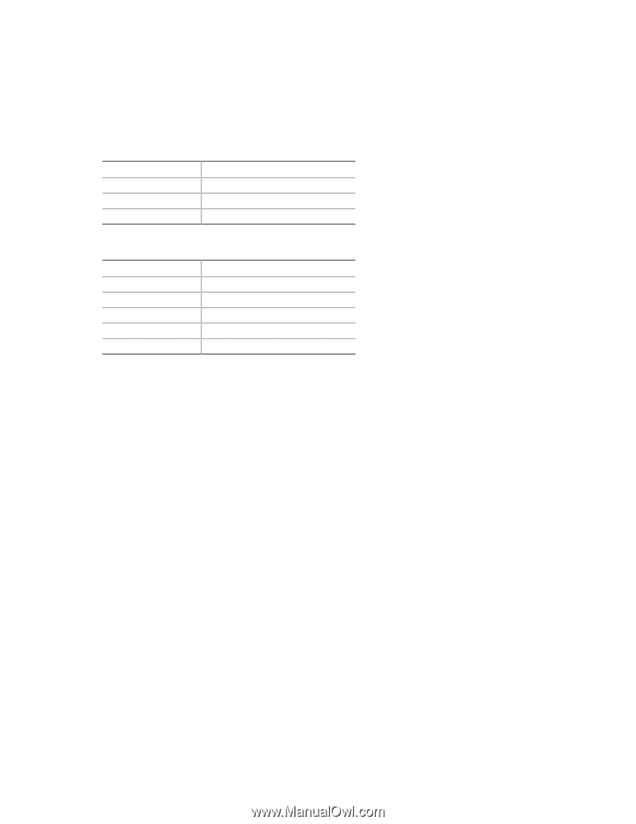
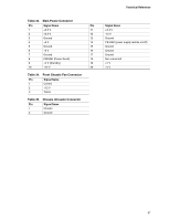
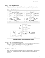
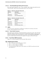
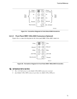
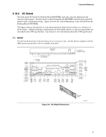
Intel Desktop Board D865PERL Technical Product Specification 2.8.3.2.3 Power/Sleep/Message Waiting LED Connector Pins 2 and 4 can be connected to a one- or two-color LED. Table 39 shows the possible states for a one-color LED. Table 40 shows the possible states for a two-color LED. Table 39. States for a One-Color Power LED LED State Off Steady Green Blinking Green Description Power off/sleeping Running Running/message waiting Table 40. States for a Two-Color Power LED LED State Description Off Power off Steady Green Running Blinking Green Running/message waiting Steady Yellow Sleeping Blinking Yellow Sleeping/message waiting ✏ NOTE To use the message waiting function, ACPI must be enabled in the operating system and a message-capturing application must be invoked. 2.8.3.2.4 Power Switch Connector Pins 6 and 8 can be connected to a front panel momentary-contact power switch. The switch must pull the SW_ON# pin to ground for at least 50 ms to signal the power supply to switch on or off. (The time requirement is due to internal debounce circuitry on the Desktop Board D865PERL.) At least two seconds must pass before the power supply will recognize another on/off signal. 2.8.3.3 Front Panel USB Connectors Figure 25 is a connection diagram for the front panel USB connectors. # INTEGRATOR'S NOTES • The +5 V DC power on the USB connector is fused. • Pins 1, 3, 5, and 7 comprise one USB port. • Pins 2, 4, 6, and 8 comprise one USB port. • Use only a front panel USB connector that conforms to the USB 2.0 specification for highspeed USB devices. 72
-
 1
1 -
2
-
3
-
4
-
5
-
6
-
7
-
8
-
9
-
10
-
11
-
12
-
13
-
14
-
15
-
16
-
17
-
18
-
19
-
20
-
21
-
22
-
23
-
24
-
25
-
26
-
27
-
28
-
29
-
30
-
31
-
32
-
33
-
34
-
35
-
36
-
37
-
38
-
39
-
40
-
41
-
42
-
43
-
44
-
45
-
46
-
47
-
48
-
49
-
50
-
51
-
52
-
53
-
54
-
55
-
56
-
57
-
58
-
59
-
60
-
61
-
62
-
63
-
64
-
65
-
66
-
 67
67 -
 68
68 -
 69
69 -
 70
70 -
 71
71 -
 72
72 -
 73
73 -
 74
74 -
 75
75 -
 76
76 -
 77
77 -
78
-
79
-
80
-
81
-
82
-
83
-
84
-
85
-
86
-
87
-
88
-
89
-
90
-
91
-
92
-
93
-
94
-
95
-
96
-
97
-
98
-
99
-
100
-
101
-
102
-
103
-
104
-
105
-
106
-
107
-
108
-
109
-
110
-
111
-
112
-
113
-
114
-
115
-
116
-
117
-
118
-
119
-
120
-
121
-
122
-
123
-
124
-
125
-
126
-
127
-
128
-
129
-
130
-
131
-
132
 |
 |