Intel BOXD865PERL Product Specification - Page 8

s, Tables

Page 8 highlights

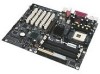
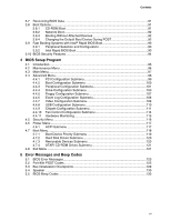
Intel Desktop Board D865PERL Technical Product Specification Figures 1. Desktop Board D865PERL Components 14 2. Block Diagram ...15 3. Memory Channel Configuration 23 4. Examples of Dual Channel Configuration with Dynamic Mode 24 5. Example of Dual Channel Configuration without Dynamic Mode 25 6. Examples of Single Channel Configuration with Dynamic Mode 26 7. Examples of Single Channel Configuration without Dynamic Mode 27 8. Intel 865PE Chipset Block Diagram 28 9. Back Panel Connectors for 6-Channel Audio Subsystem 35 10. 6-Channel Audio Subsystem Block Diagram 35 11. Back Panel Audio Connector Options for Flex 6 Audio Subsystem 36 12. Adapter for S/PDIF Back Panel Connector 37 13. Flex 6 Audio Subsystem Block Diagram 37 14. LAN Connector LED Locations 39 15. LAN Connector LED Locations 40 16. Thermal Monitoring...42 17. Location of the Standby Power Indicator LED 49 18. Detailed System Memory Address Map 52 19. Back Panel Connectors 60 20. Audio Connectors ...63 21. Power and Hardware Control Connectors 65 22. D865PERL Add-in Board and Peripheral Interface Connectors 68 23. External I/O Connectors 70 24. Connection Diagram for Front Panel Connector 71 25. Connection Diagram for Front Panel USB Connectors 73 26. Connection Diagram for Front Panel IEEE 1394a-2000 Connectors 73 27. Location of the Jumper Blocks 74 28. Board Dimensions ...76 29. I/O Shield Dimensions 77 30. Localized High Temperature Zones 81 Tables 1. Feature Summary...12 2. Manufacturing Options 13 3. Specifications ...17 4. Supported System Bus Frequency and Memory Speed Combinations 21 5. Supported Memory Configurations 22 6. Characteristics of Dual/Single Channel Configuration with/without Dynamic Mode.....23 7. LAN Connector LED States 40 8. LAN Connector LED States 41 9. Effects of Pressing the Power Switch 44 10. Power States and Targeted System Power 45 11. Wake-up Devices and Events 46 12. Fan Connector Function/Operation 47 13. System Memory Map 53 viii

  • 1
  • 2
  • 3
  • 4
  • 5
  • 6
  • 7
  • 8
  • 9
  • 10
  • 11
  • 12
  • 13
  • 14
  • 15
  • 16
  • 17
  • 18
  • 19
  • 20
  • 21
  • 22
  • 23
  • 24
  • 25
  • 26
  • 27
  • 28
  • 29
  • 30
  • 31
  • 32
  • 33
  • 34
  • 35
  • 36
  • 37
  • 38
  • 39
  • 40
  • 41
  • 42
  • 43
  • 44
  • 45
  • 46
  • 47
  • 48
  • 49
  • 50
  • 51
  • 52
  • 53
  • 54
  • 55
  • 56
  • 57
  • 58
  • 59
  • 60
  • 61
  • 62
  • 63
  • 64
  • 65
  • 66
  • 67
  • 68
  • 69
  • 70
  • 71
  • 72
  • 73
  • 74
  • 75
  • 76
  • 77
  • 78
  • 79
  • 80
  • 81
  • 82
  • 83
  • 84
  • 85
  • 86
  • 87
  • 88
  • 89
  • 90
  • 91
  • 92
  • 93
  • 94
  • 95
  • 96
  • 97
  • 98
  • 99
  • 100
  • 101
  • 102
  • 103
  • 104
  • 105
  • 106
  • 107
  • 108
  • 109
  • 110
  • 111
  • 112
  • 113
  • 114
  • 115
  • 116
  • 117
  • 118
  • 119
  • 120
  • 121
  • 122
  • 123
  • 124
  • 125
  • 126
  • 127
  • 128
  • 129
  • 130
  • 131
  • 132

Intel Desktop Board D865PERL Technical Product Specification
viii
Figures
1.
Desktop Board D865PERL Components
....................................................................
14
2.
Block Diagram
............................................................................................................
15
3.
Memory Channel Configuration
..................................................................................
23
4.
Examples of Dual Channel Configuration with Dynamic Mode
...................................
24
5.
Example of Dual Channel Configuration without Dynamic Mode
................................
25
6.
Examples of Single Channel Configuration with Dynamic Mode
.................................
26
7.
Examples of Single Channel Configuration without Dynamic Mode
............................
27
8.
Intel 865PE Chipset Block Diagram
............................................................................
28
9.
Back Panel Connectors for 6-Channel Audio Subsystem
...........................................
35
10.
6-Channel Audio Subsystem Block Diagram
..............................................................
35
11.
Back Panel Audio Connector Options for Flex 6 Audio Subsystem
............................
36
12.
Adapter for S/PDIF Back Panel Connector
.................................................................
37
13.
Flex 6 Audio Subsystem Block Diagram
.....................................................................
37
14.
LAN Connector LED Locations
...................................................................................
39
15.
LAN Connector LED Locations
...................................................................................
40
16.
Thermal Monitoring
.....................................................................................................
42
17.
Location of the Standby Power Indicator LED
............................................................
49
18.
Detailed System Memory Address Map
......................................................................
52
19.
Back Panel Connectors
..............................................................................................
60
20.
Audio Connectors
.......................................................................................................
63
21.
Power and Hardware Control Connectors
..................................................................
65
22.
D865PERL Add-in Board and Peripheral Interface Connectors
..................................
68
23.
External I/O Connectors
.............................................................................................
70
24.
Connection Diagram for Front Panel Connector
.........................................................
71
25.
Connection Diagram for Front Panel USB Connectors
...............................................
73
26.
Connection Diagram for Front Panel IEEE 1394a-2000 Connectors
..........................
73
27.
Location of the Jumper Blocks
....................................................................................
74
28.
Board Dimensions
......................................................................................................
76
29.
I/O Shield Dimensions
................................................................................................
77
30.
Localized High Temperature Zones
............................................................................
81
Tables
1.
Feature Summary
.......................................................................................................
12
2.
Manufacturing Options
...............................................................................................
13
3.
Specifications
.............................................................................................................
17
4.
Supported System Bus Frequency and Memory Speed Combinations
.......................
21
5.
Supported Memory Configurations
.............................................................................
22
6.
Characteristics of Dual/Single Channel Configuration with/without Dynamic Mode
.....
23
7.
LAN Connector LED States
........................................................................................
40
8.
LAN Connector LED States
........................................................................................
41
9.
Effects of Pressing the Power Switch
.........................................................................
44
10.
Power States and Targeted System Power
................................................................
45
11.
Wake-up Devices and Events
.....................................................................................
46
12.
Fan Connector Function/Operation
.............................................................................
47
13.
System Memory Map
..................................................................................................
53