Intel BOXD865PERL Product Specification - Page 67
Table 33., Main Power Connector, Table 34., Front Chassis Fan Connector, Table 35., Chassis
 |
UPC - 735858160056
View all Intel BOXD865PERL manuals
Add to My Manuals
Save this manual to your list of manuals |
Page 67 highlights
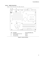
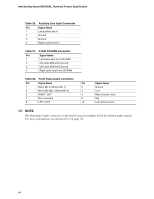
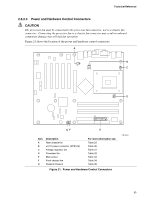
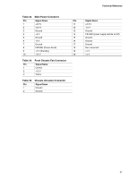
Technical Reference Table 33. Main Power Connector Pin Signal Name Pin 1 +3.3 V 11 2 +3.3 V 12 3 Ground 13 4 +5 V 14 5 Ground 15 6 +5 V 16 7 Ground 17 8 PWRGD (Power Good) 18 9 +5 V (Standby) 19 10 +12 V 20 Table 34. Front Chassis Fan Connector Pin Signal Name 1 Control 2 +12 V 3 TACH Table 35. Chassis Intrusion Connector Pin Signal Name 1 Intruder 2 Ground Signal Name +3.3 V -12 V Ground PS-ON# (power supply remote on/off) Ground Ground Ground Not connected +5 V +5 V 67
-
 1
1 -
2
-
3
-
4
-
5
-
6
-
7
-
8
-
9
-
10
-
11
-
12
-
13
-
14
-
15
-
16
-
17
-
18
-
19
-
20
-
21
-
22
-
23
-
24
-
25
-
26
-
27
-
28
-
29
-
30
-
31
-
32
-
33
-
34
-
35
-
36
-
37
-
38
-
39
-
40
-
41
-
42
-
43
-
44
-
45
-
46
-
47
-
48
-
49
-
50
-
51
-
52
-
53
-
54
-
55
-
56
-
57
-
58
-
59
-
60
-
61
-
 62
62 -
 63
63 -
 64
64 -
 65
65 -
 66
66 -
 67
67 -
 68
68 -
 69
69 -
 70
70 -
 71
71 -
 72
72 -
73
-
74
-
75
-
76
-
77
-
78
-
79
-
80
-
81
-
82
-
83
-
84
-
85
-
86
-
87
-
88
-
89
-
90
-
91
-
92
-
93
-
94
-
95
-
96
-
97
-
98
-
99
-
100
-
101
-
102
-
103
-
104
-
105
-
106
-
107
-
108
-
109
-
110
-
111
-
112
-
113
-
114
-
115
-
116
-
117
-
118
-
119
-
120
-
121
-
122
-
123
-
124
-
125
-
126
-
127
-
128
-
129
-
130
-
131
-
132
 |
 |

Technical Reference
67
Table 33.
Main Power Connector
Pin
Signal Name
Pin
Signal Name
1
+3.3 V
11
+3.3 V
2
+3.3 V
12
-12 V
3
Ground
13
Ground
4
+5 V
14
PS-ON# (power supply remote on/off)
5
Ground
15
Ground
6
+5 V
16
Ground
7
Ground
17
Ground
8
PWRGD (Power Good)
18
Not connected
9
+5 V (Standby)
19
+5 V
10
+12 V
20
+5 V
Table 34.
Front Chassis Fan Connector
Pin
Signal Name
1
Control
2
+12 V
3
TACH
Table 35.
Chassis Intrusion Connector
Pin
Signal Name
1
Intruder
2
Ground