Intel D201GLY Product Guide - Page 30
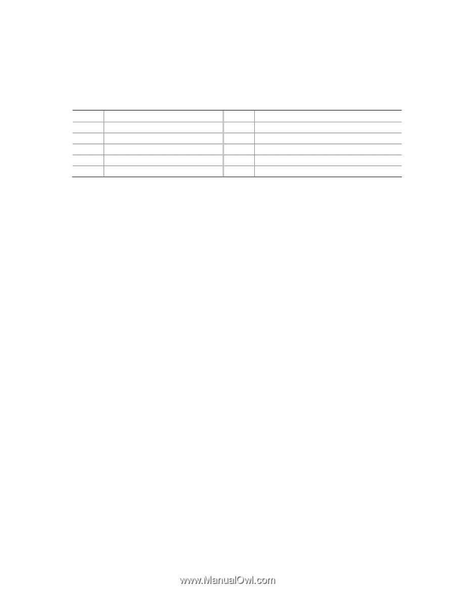
Installing a Front Panel Audio Solution, Table 4. Front Panel Audio Header Signal Names
 |
UPC - 735858193702
View all Intel D201GLY manuals
Add to My Manuals
Save this manual to your list of manuals |
Page 30 highlights
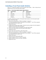
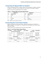
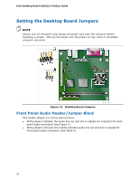
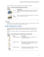
Intel Desktop Board D201GLY Product Guide Installing a Front Panel Audio Solution Figure 10, A shows the location of the front panel audio header. Table 4 shows the pin assignments for the front panel audio header. Table 4. Front Panel Audio Header Signal Names Pin Signal Name 1 MIC 3 MIC-BIAS 5 FP_OUT_R 7 AUD_5V 9 FP_OUT_L Pin Signal Name 2 AUD_GND 4 AUD_GND 6 FP_RETURN_R 8 KEY 10 FP_RETURN_L To install a cable that connects a front panel audio solution to the front panel audio header, follow these steps: 1. Observe the precautions in "Before You Begin" on page 21. 2. Turn off all peripheral devices connected to the computer. Turn off the computer and disconnect the AC power cord. 3. Remove the cover. 4. Locate the front panel audio header. Remove the two jumpers from the header to disable the back panel audio connectors. 5. Install a correctly keyed and shielded front panel audio cable. 6. Connect the audio cable to the front panel audio solution. 7. Replace the cover. To restore back panel operations, follow these steps: 1. Observe the precautions in "Before You Begin" on page 21. 2. Turn off all peripheral devices connected to the computer. Turn off the computer and disconnect the AC power cord. 3. Remove the cover. 4. Remove the front panel audio cable. 5. Install a jumper on pins 5-6 (rear R channel). 6. Install a jumper on pins 9-10 (rear L channel). 7. Replace the cover. 30
-
 1
1 -
2
-
3
-
4
-
5
-
6
-
7
-
8
-
9
-
10
-
11
-
12
-
13
-
14
-
15
-
16
-
17
-
18
-
19
-
20
-
21
-
22
-
23
-
24
-
 25
25 -
 26
26 -
 27
27 -
 28
28 -
 29
29 -
 30
30 -
 31
31 -
 32
32 -
 33
33 -
 34
34 -
 35
35 -
36
-
37
-
38
-
39
-
40
-
41
-
42
-
43
-
44
-
45
-
46
-
47
-
48
-
49
-
50
-
51
-
52
-
53
-
54
-
55
-
56
 |
 |