Intel D201GLY Product Guide - Page 31
Connecting Hi-Speed USB 2.0 Headers, Connecting the Front Panel Header
 |
UPC - 735858193702
View all Intel D201GLY manuals
Add to My Manuals
Save this manual to your list of manuals |
Page 31 highlights
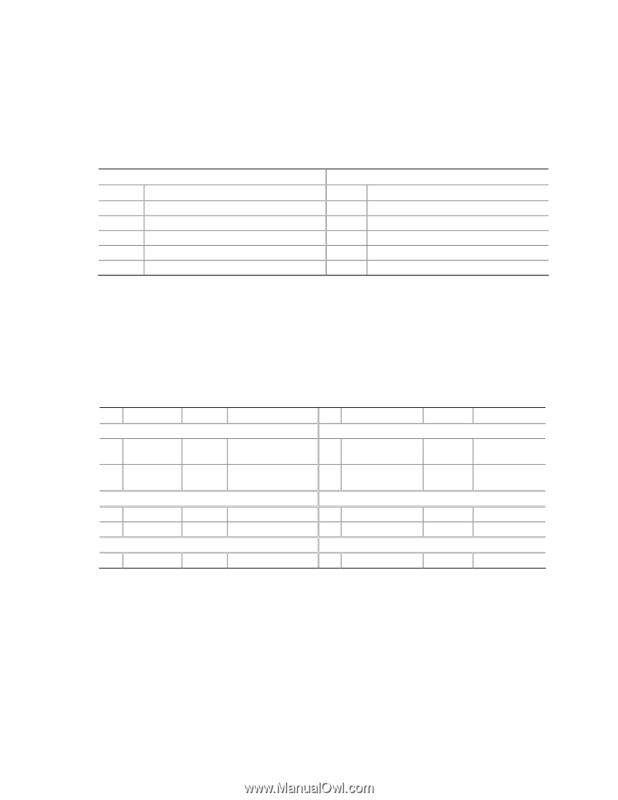
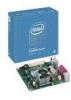
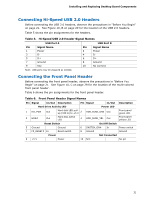
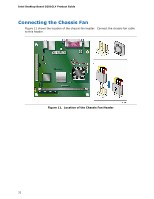
Installing and Replacing Desktop Board Components Connecting Hi-Speed USB 2.0 Headers Before connecting the USB 2.0 headers, observe the precautions in "Before You Begin" on page 21. See Figure 10, B on page 29 for the location of the USB 2.0 headers. Table 5 shows the pin assignments for the headers. Table 5. Hi-Speed USB 2.0 Header Signal Names USB Port A USB Port B Pin Signal Name 1 Power 3 D- 5 D+ 7 Ground 9 Key Pin Signal Name 2 Power 4 D- 6 D+ 8 Ground 10 No connect Note: USB ports may be assigned as needed. Connecting the Front Panel Header Before connecting the front panel header, observe the precautions in "Before You Begin" on page 21. See Figure 10, C on page 29 for the location of the multi-colored front panel header. Table 6 shows the pin assignments for the front panel header. Table 6. Front Panel Header Signal Names Pin Signal In/Out Description Pin Signal In/Out Hard Drive Activity LED Power LED 1 HD_PWR Out Hard disk LED pullup (330 Ω) to +5 V 2 HDR_BLNK_GRN Out 3 HDA# Out Hard disk active LED 4 HDR_BLNK_YEL Out Description Front panel green LED Front panel yellow LED Reset Switch On/Off Switch 5 Ground 7 FP_RESET# In Ground Reset switch 6 SWITCH_ON# In 8 Ground Power switch Ground Power Not Connected 9 +5 V Power 10 N/C No pin 31
-
 1
1 -
2
-
3
-
4
-
5
-
6
-
7
-
8
-
9
-
10
-
11
-
12
-
13
-
14
-
15
-
16
-
17
-
18
-
19
-
20
-
21
-
22
-
23
-
24
-
25
-
 26
26 -
 27
27 -
 28
28 -
 29
29 -
 30
30 -
 31
31 -
 32
32 -
 33
33 -
 34
34 -
 35
35 -
 36
36 -
37
-
38
-
39
-
40
-
41
-
42
-
43
-
44
-
45
-
46
-
47
-
48
-
49
-
50
-
51
-
52
-
53
-
54
-
55
-
56
 |
 |