Intel D2550DC2 Technical product specification - Page 42
Table 10., Component-side Connectors and Headers Shown
 |
View all Intel D2550DC2 manuals
Add to My Manuals
Save this manual to your list of manuals |
Page 42 highlights
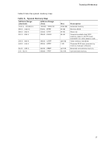
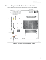
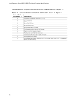
Intel Desktop Board D2550DC2 Technical Product Specification Table 10 lists the component-side connectors and headers identified in Figure 11. Table 10. Component-side Connectors and Headers Shown in Figure 11 Item/callout from Figure 11 A B C Description Processor core power connector (2 x 12) SATA connector SATA connector D System fan header E Front panel header F Front panel USB 2.0 header G Front panel wireless activity LED header H Piezo/monotonic speaker header I PCI Express Full-/Half-Mini Card slot J Conventional PCI bus add-in card connector K Front panel audio header L Front panel USB header supports Intel Z-U130 USB Solid-State Drive or compatible device (brown-colored) 42
-
 1
1 -
2
-
3
-
4
-
5
-
6
-
7
-
8
-
9
-
10
-
11
-
12
-
13
-
14
-
15
-
16
-
17
-
18
-
19
-
20
-
21
-
22
-
23
-
24
-
25
-
26
-
27
-
28
-
29
-
30
-
31
-
32
-
33
-
34
-
35
-
36
-
 37
37 -
 38
38 -
 39
39 -
 40
40 -
 41
41 -
 42
42 -
 43
43 -
 44
44 -
 45
45 -
 46
46 -
 47
47 -
48
-
49
-
50
-
51
-
52
-
53
-
54
-
55
-
56
-
57
-
58
-
59
-
60
-
61
-
62
-
63
-
64
-
65
-
66
-
67
-
68
-
69
-
70
-
71
-
72
-
73
-
74
-
75
-
76
-
77
-
78
-
79
-
80
-
81
-
82
-
83
-
84
-
85
-
86
-
87
-
88
-
89
-
90
 |
 |
Intel Desktop Board D2550DC2 Technical Product Specification
42
Table 10 lists the component-side connectors and headers identified in Figure 11.
Table 10.
Component-side Connectors and Headers Shown in Figure 11
Item/callout
from Figure 11
Description
A
Processor core power connector (2 x 12)
B
SATA connector
C
SATA connector
D
System fan header
E
Front panel header
F
Front panel USB 2.0 header
G
Front panel wireless activity LED header
H
Piezo/monotonic speaker header
I
PCI Express Full-/Half-Mini Card slot
J
Conventional PCI bus add-in card connector
K
Front panel audio header
L
Front panel USB header supports Intel Z-U130 USB Solid-State Drive or compatible
device (brown-colored)