Intel D2550DC2 Technical product specification - Page 56
Thermal Specifications Guideline, Heatsink Design Guideline
 |
View all Intel D2550DC2 manuals
Add to My Manuals
Save this manual to your list of manuals |
Page 56 highlights
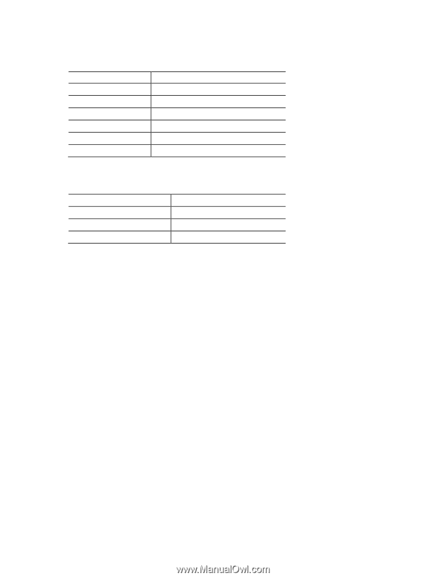
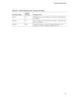
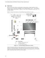
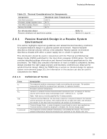
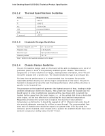
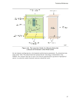
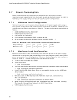
Intel Desktop Board D2550DC2 Technical Product Specification 2.6.1.2 Thermal Specifications Guideline Terms TA TJ ΨJA TIM TDP TA external Requirements ≤ 50 °C ≤ 100 °C ≤ 3.85 °C/W Honeywell PCM45F 10 W ≤ 35 °C 2.6.1.3 Heatsink Design Guideline Maximum heatsink size (Note) 87 x 52 x 29 mm Heatsink mass ≤ 63.6 grams Retention type Spring loaded fasteners Heatsink preload 13.2 lb Note: Refers to the heatsink installed on the board. 2.6.1.4 Chassis Design Guideline The pin fin heatsink design used on this board will be able to dissipate up to 10 W of processor power in most of the passively enabled system chassis. This board is targeted for 3-7 liters volumetric or larger, desktop/tower orientation, mini-ITX and microATX chassis with a system fan. The recommended fan type is an exhaust fan. For best thermal performance, it is recommended that the system fan provide reasonable airflow directly over all the major components on the board. The pin fin heatsink is designed to have the best thermal performance when airflow direction is parallel to the heatsink fins. The processor on the board will generate the highest amount of heat, leading to high ambient temperature within the chassis. The system fan should be located near the board region in order to effectively regulate airflow (see Figure 18). A system fan located further away from the board region, i.e., at the optical disk drive or hard disk drive region, will be less effective in controlling the local ambient temperature. Regardless of where the system fan is located, the maximum local ambient temperature as defined by TA should be capped at 50 °C. Chassis inlet vents should also provide adequate openings for airflow to pass through. The recommended freearea-ratio of chassis vents should be equal to or greater than 0.53. By using the reference pin fin heatsink, most chassis with a system fan enabled should have local ambient temperature safely below the 50 °C limit. 56
-
 1
1 -
2
-
3
-
4
-
5
-
6
-
7
-
8
-
9
-
10
-
11
-
12
-
13
-
14
-
15
-
16
-
17
-
18
-
19
-
20
-
21
-
22
-
23
-
24
-
25
-
26
-
27
-
28
-
29
-
30
-
31
-
32
-
33
-
34
-
35
-
36
-
37
-
38
-
39
-
40
-
41
-
42
-
43
-
44
-
45
-
46
-
47
-
48
-
49
-
50
-
 51
51 -
 52
52 -
 53
53 -
 54
54 -
 55
55 -
 56
56 -
 57
57 -
 58
58 -
 59
59 -
 60
60 -
 61
61 -
62
-
63
-
64
-
65
-
66
-
67
-
68
-
69
-
70
-
71
-
72
-
73
-
74
-
75
-
76
-
77
-
78
-
79
-
80
-
81
-
82
-
83
-
84
-
85
-
86
-
87
-
88
-
89
-
90
 |
 |