Intel D510MO Product Specification - Page 22
Real-Time Clock Subsystem, 1.7 Legacy I/O Controller, 1.7.1 Serial Port Headers - memory compatibility
 |
View all Intel D510MO manuals
Add to My Manuals
Save this manual to your list of manuals |
Page 22 highlights
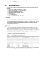
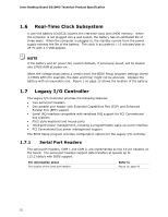
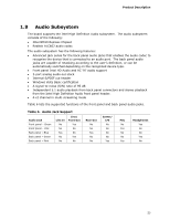
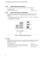
Intel Desktop Board D510MO Technical Product Specification 1.6 Real-Time Clock Subsystem A coin-cell battery (CR2032) powers the real-time clock and CMOS memory. When the computer is not plugged into a wall socket, the battery has an estimated life of three years. When the computer is plugged in, the standby current from the power supply extends the life of the battery. The clock is accurate to ± 13 minutes/year at 25 ºC with 3.3 VSB applied. NOTE If the battery and AC power fail, custom defaults, if previously saved, will be loaded into CMOS RAM at power-on. When the voltage drops below a certain level, the BIOS Setup program settings stored in CMOS RAM (for example, the date and time) might not be accurate. Replace the battery with an equivalent one. Figure 1 on page 13 shows the location of the battery. 1.7 Legacy I/O Controller The Legacy I/O Controller provides the following features: • Two serial port headers • One parallel port header with Extended Capabilities Port (ECP) and Enhanced Parallel Port (EPP) support • Serial IRQ interface compatible with serialized IRQ support for PCI Conventional bus systems • PS/2-style keyboard and mouse ports • Intelligent power management, including a programmable wake-up event interface • PCI Conventional bus power management support The BIOS Setup program provides configuration options for the Legacy I/O controller. 1.7.1 Serial Port Headers The serial port headers, COM 1 and COM 2, are implemented as two 10-pin headers on the board. The serial port headers support data transfers at speeds up to 115.2 kbits/s with BIOS support. For information about The location of the serial port headers Refer to Figure 10, page 43 22
-
 1
1 -
2
-
3
-
4
-
5
-
6
-
7
-
8
-
9
-
10
-
11
-
12
-
13
-
14
-
15
-
16
-
 17
17 -
 18
18 -
 19
19 -
 20
20 -
 21
21 -
 22
22 -
 23
23 -
 24
24 -
 25
25 -
 26
26 -
 27
27 -
28
-
29
-
30
-
31
-
32
-
33
-
34
-
35
-
36
-
37
-
38
-
39
-
40
-
41
-
42
-
43
-
44
-
45
-
46
-
47
-
48
-
49
-
50
-
51
-
52
-
53
-
54
-
55
-
56
-
57
-
58
-
59
-
60
-
61
-
62
-
63
-
64
-
65
-
66
-
67
-
68
-
69
-
70
-
71
-
72
-
73
-
74
-
75
-
76
-
77
-
78
-
79
-
80
-
81
-
82
-
83
-
84
-
85
-
86
-
87
-
88
-
89
-
90
-
91
-
92
 |
 |