Intel D510MO Product Specification - Page 53
Front Panel USB Headers, Connection Diagram for Front Panel USB Header
 |
View all Intel D510MO manuals
Add to My Manuals
Save this manual to your list of manuals |
Page 53 highlights
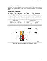
Technical Reference 2.2.2.5 Front Panel USB Headers Figure 12 and Figure 13 are connection diagrams for the front panel USB headers. NOTE • The +5 VDC power on the USB headers is fused. • Use only a front panel USB connector that conforms to the USB 2.0 specification for high-speed USB devices. Figure 12. Connection Diagram for Front Panel USB Header Figure 13. Connection Diagram for Front Panel USB Header (with Intel Z-U130 USB Solid-State Drive, or Compatible Device, Support) 53
-
 1
1 -
2
-
3
-
4
-
5
-
6
-
7
-
8
-
9
-
10
-
11
-
12
-
13
-
14
-
15
-
16
-
17
-
18
-
19
-
20
-
21
-
22
-
23
-
24
-
25
-
26
-
27
-
28
-
29
-
30
-
31
-
32
-
33
-
34
-
35
-
36
-
37
-
38
-
39
-
40
-
41
-
42
-
43
-
44
-
45
-
46
-
47
-
 48
48 -
 49
49 -
 50
50 -
 51
51 -
 52
52 -
 53
53 -
 54
54 -
 55
55 -
 56
56 -
 57
57 -
 58
58 -
59
-
60
-
61
-
62
-
63
-
64
-
65
-
66
-
67
-
68
-
69
-
70
-
71
-
72
-
73
-
74
-
75
-
76
-
77
-
78
-
79
-
80
-
81
-
82
-
83
-
84
-
85
-
86
-
87
-
88
-
89
-
90
-
91
-
92
 |
 |
Technical Reference
53
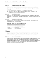
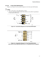
2.2.2.5
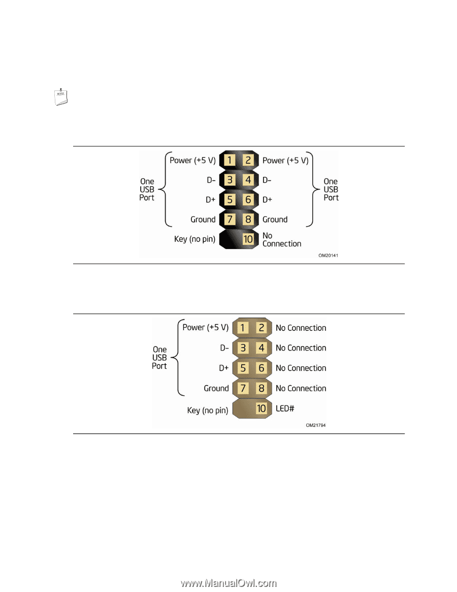
Front Panel USB Headers
Figure 12 and Figure 13 are connection diagrams for the front panel USB headers.
NOTE
•
The +5 VDC power on the USB headers is fused.
•
Use only a front panel USB connector that conforms to the USB 2.0 specification
for high-speed USB devices.
Figure 12.
Connection Diagram for Front Panel USB Header
Figure 13.
Connection Diagram for Front Panel USB Header
(with Intel Z-U130 USB Solid-State Drive, or Compatible Device, Support)