Intel D510MO Product Specification - Page 57
Electrical Considerations, 2.5.1 Fan Header Current Capability, 2.5.2 Add-in Board Considerations - case
 |
View all Intel D510MO manuals
Add to My Manuals
Save this manual to your list of manuals |
Page 57 highlights
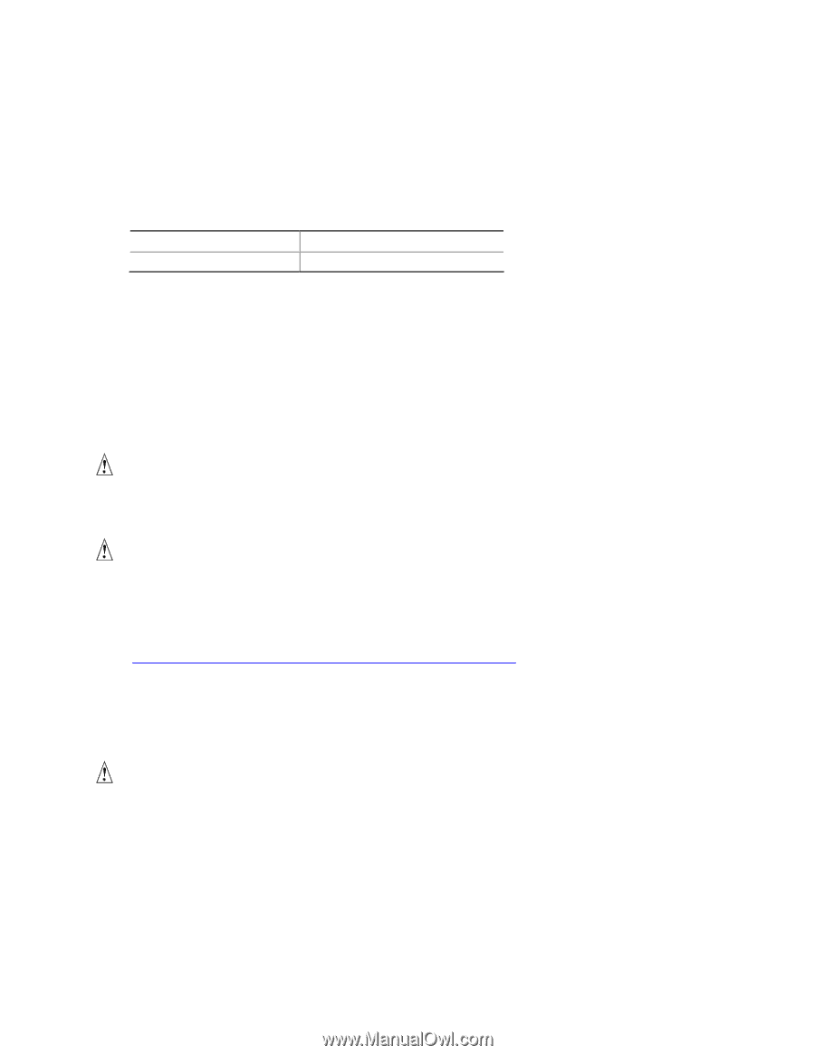
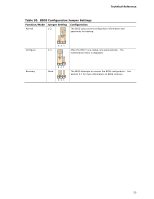
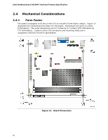
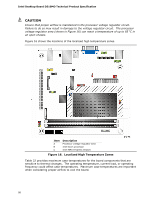
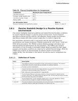
Technical Reference 2.5 Electrical Considerations 2.5.1 Fan Header Current Capability Table 31 lists the current capability of the fan header. Table 31. Fan Header Current Capability Fan Header Maximum Available Current Chassis fan 1.0 A 2.5.2 Add-in Board Considerations The board is designed to provide 2 A (average) of +5 V current for the PCI Conventional slot. The total +5 V current draw for the PCI Conventional expansion slot (total load) must not exceed 2 A. 2.6 Thermal Considerations CAUTION A chassis with a maximum internal ambient temperature of 38 oC at the processor fan inlet is a requirement. CAUTION Failure to ensure appropriate airflow may result in reduced performance of both the processor and/or voltage regulator or, in some instances, damage to the board. For a list of chassis that have been tested with Intel Desktop Boards please refer to the following website: http://developer.intel.com/design/motherbd/cooling.htm All responsibility for determining the adequacy of any thermal or system design remains solely with the reader. Intel makes no warranties or representations that merely following the instructions presented in this document will result in a system with adequate thermal performance. CAUTION Ensure that the ambient temperature does not exceed the board's maximum operating temperature. Failure to do so could cause components to exceed their maximum case temperature and malfunction. For information about the maximum operating temperature, see the environmental specifications in Section 2.9. 57
-
 1
1 -
2
-
3
-
4
-
5
-
6
-
7
-
8
-
9
-
10
-
11
-
12
-
13
-
14
-
15
-
16
-
17
-
18
-
19
-
20
-
21
-
22
-
23
-
24
-
25
-
26
-
27
-
28
-
29
-
30
-
31
-
32
-
33
-
34
-
35
-
36
-
37
-
38
-
39
-
40
-
41
-
42
-
43
-
44
-
45
-
46
-
47
-
48
-
49
-
50
-
51
-
 52
52 -
 53
53 -
 54
54 -
 55
55 -
 56
56 -
 57
57 -
 58
58 -
 59
59 -
 60
60 -
 61
61 -
 62
62 -
63
-
64
-
65
-
66
-
67
-
68
-
69
-
70
-
71
-
72
-
73
-
74
-
75
-
76
-
77
-
78
-
79
-
80
-
81
-
82
-
83
-
84
-
85
-
86
-
87
-
88
-
89
-
90
-
91
-
92
 |
 |