Intel D845GVFN English Product Guide - Page 31
Connecting Internal Headers
 |
View all Intel D845GVFN manuals
Add to My Manuals
Save this manual to your list of manuals |
Page 31 highlights
Installing and Replacing Desktop Board Components Connecting Internal Headers Follow the instructions below to connect the USB, power LED, and front panel solutions. See Figure 8 for pin assignments. A G 1 2 3 4 B 5 6 7 9 10 F 1 2 3 4 5 6 7 8 10 2 1 C 1 2 3 4 5 6 7 8 9 13 E Item A B C D E F G D Description Auxiliary line in ATAPI CD ROM Front panel Alternate power LED Chassis intrusion Front panel USB Front panel audio OM17426 Figure 8. Location of Internal Headers 31
-
 1
1 -
2
-
3
-
4
-
5
-
6
-
7
-
8
-
9
-
10
-
11
-
12
-
13
-
14
-
15
-
16
-
17
-
18
-
19
-
20
-
21
-
22
-
23
-
24
-
25
-
 26
26 -
 27
27 -
 28
28 -
 29
29 -
 30
30 -
 31
31 -
 32
32 -
 33
33 -
 34
34 -
 35
35 -
 36
36 -
37
-
38
-
39
-
40
-
41
-
42
-
43
-
44
-
45
-
46
-
47
-
48
-
49
-
50
-
51
-
52
-
53
-
54
-
55
-
56
-
57
-
58
 |
 |

Installing and Replacing Desktop Board Components
31
Connecting Internal Headers
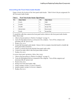
Follow the instructions below to connect the USB, power LED, and front panel solutions.
See
Figure 8 for pin assignments.
OM17426
2
1
3
4
5
6
7
10
B
8
C
1
3
A
2
1
3
4
5
6
7
10
9
2
1
3
4
5
6
7
9
8
D
E
G
F
1
2
Item
Description
A
Auxiliary line in
B
ATAPI CD ROM
C
Front panel
D
Alternate power LED
E
Chassis intrusion
F
Front panel USB
G
Front panel audio
Figure 8.
Location of Internal Headers