Intel Desktop Board D845GVFN Product Guide
vi
Locating the PCI Bus Add-in Card, Diskette Drive, and IDE Connectors
.............................
36
Setting the BIOS Configuration Jumper Block
.....................................................................
37
Clearing Passwords
............................................................................................................
38
Back Panel Connectors
.......................................................................................................
39
Replacing the Battery
..........................................................................................................
40
3
BIOS
Using the BIOS Setup Program
..........................................................................................
45
Updating the BIOS
..............................................................................................................
45
Updating the BIOS with the Intel
®
Express BIOS Update Utility
.................................
45
Updating the BIOS with the Intel
®
Iflash BIOS Update Utility
......................................
45
Obtaining the BIOS Update File
.................................................................................
45
Updating the BIOS
.....................................................................................................
46
Recovering the BIOS
..................................................................................................
46
4
Desktop Board Resources
Memory Map
.......................................................................................................................
49
DMA Channels
....................................................................................................................
49
Interrupts
.............................................................................................................................
50
A
Error Messages and Indicators
BIOS Beep Codes
...............................................................................................................
51
BIOS Error Messages
.........................................................................................................
52
B
Regulatory Compliance
Safety Regulations
..............................................................................................................
55
European Union Declaration of Conformity Statement
........................................................
55
Product Ecology Statements
...............................................................................................
56
EMC Regulations
................................................................................................................
57
Product Certification Markings (Board Level)
......................................................................
58
Figures
1. Desktop Board Components
.........................................................................................
11
2.
Installing the I/O Shield
.................................................................................................
24
3.
Desktop Board Mounting Screw Holes
.........................................................................
25
4. Installing a Processor
...................................................................................................
26
5.
Connecting the Processor Fan Heatsink Cable to the Processor Fan Header
..............
27
6. Installing DIMMs
...........................................................................................................
28
7.
Connecting the IDE Cable
............................................................................................
30
8. Internal Headers
...........................................................................................................
31
9.
Location of Fan Headers and Power Connectors
..........................................................
34
10. Location of the PCI Bus Add-in Card, Diskette Drive, and IDE Connectors
..................
36
11. Location of the BIOS Configuration Jumper Block
........................................................
37
12. Back Panel Connectors
................................................................................................
39
13. Removing the Battery from the Desktop Board
.............................................................
43

 1
1 2
2 3
3 4
4 5
5 6
6 7
7 8
8 9
9 10
10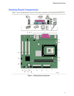 11
11 12
12