Intel D848PMB Product Guide
Intel D848PMB Manual
 |
View all Intel D848PMB manuals
Add to My Manuals
Save this manual to your list of manuals |
Intel D848PMB manual content summary:
- Intel D848PMB | Product Guide - Page 1
Intel® Desktop Board D848PMB Product Guide Order Number: C54219-002 - Intel D848PMB | Product Guide - Page 2
of the Intel® Desktop Board D848PMB Product Guide. Date October 2003 If an FCC declaration of conformity marking is present on the board, the energy and, if not installed and used in accordance with the instructions, may cause harmful interference to radio communications. However, there is - Intel D848PMB | Product Guide - Page 3
Preface This Product Guide gives information about board layout, component installation, BIOS Setup menus, and regulatory requirements for Intel® Desktop Board D848PMB. Intended Audience The Product Guide is intended for technically qualified personnel. It is not intended for general audiences. - Intel D848PMB | Product Guide - Page 4
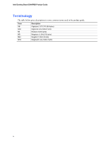
Intel Desktop Board D848PMB Product Guide Terminology The table below gives descriptions to some common terms used in the product guide. Term GB GHz KB MB Mbit MHz Description Gigabyte (1,073,741,824 bytes) Gigahertz (one billion hertz) Kilobyte (1024 bytes) Megabyte (1,048,576 bytes) Megabit - Intel D848PMB | Product Guide - Page 5
1 Desktop Board Features Manufacturing Options ...11 Supported Operating Systems 11 Desktop Board Components 12 Processor ...14 Main Memory ...15 Intel® 848P Chipset...16 Audio Subsystem ...16 Input/Output (I/O) Controller 17 LAN Subsystem (Optional)...17 LAN Subsystem Software 17 RJ-45 LAN - Intel D848PMB | Product Guide - Page 6
Intel Desktop Board D848PMB Product Guide Installing and Removing a Processor 28 Installing a Processor 28 Installing the Processor Fan Heat Sink 28 Connecting the Processor Fan Heat Sink Cable 29 Removing the Processor 29 Installing and Removing Memory a Front Panel Audio Solution 37 Add- - Intel D848PMB | Product Guide - Page 7
Devices Submenu 76 ATAPI CD-ROM Drives 77 Exit Menu ...78 5 Desktop Board Resources Memory Map ...79 DMA Channels ...79 Interrupts ...80 A Error Messages and Indicators BIOS Beep Codes...81 BIOS Error Messages ...82 B Regulatory Compliance Safety Regulations ...85 European Union Declaration - Intel D848PMB | Product Guide - Page 8
Intel Desktop Board D848PMB Product Guide Tables 1. Feature Summary...9 2. Manufacturing Options 11 3. Desktop Board Components 13 4. Supported Processors ...14 5. RJ-45 10/100 Ethernet LAN . Video Configuration Memory Map...79 37. DMA Channels ...79 38. Interrupts ...80 39. Beep Codes...81 40. BIOS - Intel D848PMB | Product Guide - Page 9
Features Table 1 describes the major features of Intel® Desktop Board D848PMB. Table 1. Feature Summary Form Factor Processor Main Memory Chipset Graphics Audio Peripheral Interfaces MicroATX 9.6-inches by 8.5-inches Support for: • Intel® Pentium® 4 processor (1.60a, 1.80a, 2a, 2.2 GHz or higher - Intel D848PMB | Product Guide - Page 10
based on system temperature • Voltage sensing to detect out of range values Related Links: For more information about Intel Desktop Board D848PMB, including the Technical Product Specification (TPS), BIOS updates, and device drivers, go to: http://support.intel.com/support/motherboards/desktop/ 10 - Intel D848PMB | Product Guide - Page 11
for Desktop Board D848PMB. Table 2. Option LAN Manufacturing Options Description Intel® 82562EX 10/100 Mbit/sec Platform LAN Connect (PLC) device and RJ-45 connector Supported Operating Systems The desktop board supports the following operating systems: • Microsoft Windows* XP • Microsoft Windows - Intel D848PMB | Product Guide - Page 12
Intel Desktop Board D848PMB Product Guide Desktop Board Components Figure 1 shows the approximate location of the major components on Desktop Board D848PMB. Line In USB 2.0 Devices AB C USB 2.0 Devices Z Y X W V U T R S Q PO N M L K J Figure 1. Desktop Board Components D E F G H I - Intel D848PMB | Product Guide - Page 13
latest information about: • Intel Desktop Board D848PMB, http://www.intel.com/design/motherbd • Processors, http://support.intel.com/support/motherboards/desktop • Audio software and utilities, http://www.intel.com/design/motherbd • LAN software and drivers, http://www.intel.com/design/motherbd 13 - Intel D848PMB | Product Guide - Page 14
processor. Related Links: Go to the following link or sections in this manual for: • The latest information on supported Intel processors for Desktop Board D848PMB http://support.intel.com/support/motherboards/desktop/ • Instructions on installing or upgrading the processor, page 28 in Chapter 2 14 - Intel D848PMB | Product Guide - Page 15
non-ECC mode) 2.5 V memory Related Links: Go to the following links or section in this manual for: • The latest list of tested memory, http://support.intel.com/support/motherboards/desktop/ • SDRAM specifications, http://www.intel.com/technology/memory/pcsdram/spec/ • Installing memory, page 30 in - Intel D848PMB | Product Guide - Page 16
Mic in or Center LFE out Related Links: Go to the following link or sections in this manual for more information about: • Audio drivers and utilities, http://support.intel.com/support/motherboards/desktop/ • Location of the internal audio connectors, page 35 in Chapter • Installing the front panel - Intel D848PMB | Product Guide - Page 17
and drivers, refer to the D848PMB link on Intel's World Wide Web site at: http://support.intel.com/support/motherboards/desktop RJ-45 LAN Connector LEDs Two LEDs are built into the RJ-45 LAN connector. Table 5 describes the LED states when the board is powered up and the 10/100 Ethernet LAN - Intel D848PMB | Product Guide - Page 18
Intel Desktop Board D848PMB Product Guide Hi-Speed USB 2.0 Support NOTE BIOS reverts all USB 2.0 ports to USB 1.1 operation. This may be required to accommodate operating systems that do not support USB 2.0. NOTE USB devices are limited to USB 1.1 transfer rates prior to operating system and driver - Intel D848PMB | Product Guide - Page 19
Desktop Board Features BIOS The BIOS provides the Power-On Self-Test (POST), the BIOS Setup program, the PCI and IDE auto-configuration utilities, and the video BIOS. The BIOS is stored in the Firmware Hub. The BIOS can be updated by following the instructions in Chapter 3 on page 47. PCI Auto - Intel D848PMB | Product Guide - Page 20
Intel Desktop Board D848PMB Product Guide Power Management Features Power management is implemented at several levels, including: • Advanced Configuration and Power Interface (ACPI) • Hardware support speed control feature can be disabled in the BIOS, resulting in the chassis fans always operating at - Intel D848PMB | Product Guide - Page 21
S3 sleep state) configuration. If the standby current necessary to support multiple wake events from the PCI and/or USB buses exceeds power supply capacity, the desktop board may lose register settings stored in memory. Related Link: For more information about standby current requirements for these - Intel D848PMB | Product Guide - Page 22
Intel Desktop Board D848PMB Product Guide USB requires the use of a USB peripheral that supports Wake from USB. Wake from PS/2 Keyboard/Mouse instructions on how to replace the battery. Real-Time Clock The desktop board has a time-of-day clock and 100-year calendar. The battery on the desktop board - Intel D848PMB | Product Guide - Page 23
how to: • Install the I/O shield • Install and remove the desktop board • Install and remove a processor and memory • Install and remove an AGP card • Connect the IDE and from its power source and from any telecommunications links, networks, or modems before performing any of the procedures described - Intel D848PMB | Product Guide - Page 24
Intel Desktop Board D848PMB Product Guide Follow these guidelines before you begin: • Always instruct you to refer computer servicing to qualified technical personnel. Installation Instructions CAUTION Follow these guidelines to meet safety and regulatory requirements when installing this board - Intel D848PMB | Product Guide - Page 25
the front of this product guide demonstrates compliance with Canadian EMC regulations There is insufficient space on this desktop board to provide instructions for replacing and disposing of the Only for Intended Applications All Intel desktop boards are evaluated as Information Technology Equipment - Intel D848PMB | Product Guide - Page 26
Intel Desktop Board D848PMB Product Guide Installing the I/O Shield The desktop board comes with an I/O shield. When installed promotes correct airflow within the chassis. Install the I/O shield before installing the desktop board in the chassis. Place the shield inside the chassis as shown in Figure - Intel D848PMB | Product Guide - Page 27
. NOTE Refer to Appendix B for regulatory requirements. Refer to your chassis manual for instructions on installing and removing the desktop board. Figure 4 shows the location of the six mounting holes for Desktop Board D848PMB. OM16352 Figure 4. Location of Desktop Board Mounting Screw Holes 27 - Intel D848PMB | Product Guide - Page 28
Sink Desktop Board D848PMB has an integrated processor fan heat sink retention mechanism (RM). For instructions on how to install the processor fan heat sink to the integrated processor fan heat sink RM, refer to the boxed processor manual or the Intel World Wide Web site at: http://support.intel - Intel D848PMB | Product Guide - Page 29
Heat Sink Cable to the Processor Fan Connector Removing the Processor For instruction on how to remove the processor fan heat sink and processor, refer to the processor installation manual or the Intel World Wide Web site at: http://support.intel.com/support/processors/pentium4/intnotes478.htm 29 - Intel D848PMB | Product Guide - Page 30
with all applicable Intel SDRAM memory specifications, the board requires DIMMs that support the Serial Presence Detect (SPD) data structure. You can access the PC Serial Presence Detect Specification at: http://www.intel.com/technology/memory/pcsdram/spec/ Desktop Board D848PMB has a single channel - Intel D848PMB | Product Guide - Page 31
Installing and Replacing Desktop Board Components Installing DIMMs CAUTION Install memory in the DIMM sockets prior to installing an AGP video card to avoid interference with the memory retention mechanism. To install DIMMs, follow these steps: 1. Observe the precautions in "Before You Begin" on - Intel D848PMB | Product Guide - Page 32
Intel Desktop Board D848PMB Product Guide Installing and Removing an AGP Card CAUTION When installing any AGP card in the desktop board, ensure that it is fully seated in the AGP connector before you power on the system. If the card is not fully seated in the - Intel D848PMB | Product Guide - Page 33
cables support the Ultra DMA-33 and ATA-66/100 transfer protocols. Each of the cables can connect two drives to the desktop board. Figure on page 23. • Attach the cable end with the single connector to the Intel desktop board (A). • Attach the cable end with the two closely spaced connectors to the - Intel D848PMB | Product Guide - Page 34
Intel Desktop Board D848PMB Product Guide Connecting the Serial ATA Cable The SATA cable (4-conductor) supports the Serial ATA protocol and connects a single drive to the desktop board. Either end of the cable can be connected to the SATA drive or the connector on the board (see Figure 10). For - Intel D848PMB | Product Guide - Page 35
Desktop Board Components Connecting Internal Headers Figure 11 shows the location of internal headers. B 1 2 3 4 5 6 7 9 10 J8A1 C A 1 2 3 4 J8B2 J9C2 D J9F1 1 2 3 4 5 6 7 8 10 J9H1 E 2468 1357 9 J9H3 12 F Item A B C D E F Description CD-ROM audio Front panel audio - Intel D848PMB | Product Guide - Page 36
Intel Desktop Board D848PMB Product Guide Connecting the Front Panel Header Before connecting the front panel header, observe the precautions in "Before You Begin" on page 23. Figure 11-D on page - Intel D848PMB | Product Guide - Page 37
Installing and Replacing Desktop Board Components Installing a Front Panel Audio Solution Figure 11-A shows the location of the front panel audio header. Table 8 shows the pin assignments for the front panel audio header. Table 8. Front Panel Audio Header Signal Names (J8A1) Pin Signal Name 1 - Intel D848PMB | Product Guide - Page 38
Intel Desktop Board D848PMB Product Guide Add-In Card and Peripheral Interface Connectors Figure 12 shows the PCI bus add-in card and peripheral interface connectors for Desktop Board D848PMB. A BCD Item A B C D G F E OM16361 Description PCI bus add-in card connector 3 PCI bus add-in card - Intel D848PMB | Product Guide - Page 39
Installing and Replacing Desktop Board Components Connecting Hardware Control and Power Cables Figure 13 shows the location of the chassis intrusion and fan headers and power connectors. Chassis rear fan 1 - Intel D848PMB | Product Guide - Page 40
Intel Desktop Board D848PMB Product Guide Connecting the Chassis Intrusion Cable Connect the chassis intrusion cable to the header shown in Figure 13. Connecting Fans Connect the processor's fan heat sink cable to the processor fan header on the board. Connect chassis fan cables to the board fan - Intel D848PMB | Product Guide - Page 41
cord from the computer before changing the jumper. Moving the jumper with the power on may result in unreliable computer operation. The location of the desktop board's BIOS configuration jumper is shown in Figure 14. 13 J8H3 OM16356 Figure 14. Location of the - Intel D848PMB | Product Guide - Page 42
Intel Desktop Board D848PMB Product Guide Clearing Passwords This procedure assumes that the board is installed in the computer and the configuration jumper block is set to normal mode. 1. Observe the precautions in "Before You Begin" on page 23. 2. - Intel D848PMB | Product Guide - Page 43
and Replacing Desktop Board Components Replacing the Battery A coin-cell battery (CR2032) powers the real-time clock and CMOS memory. When ºC with 3.3 VSB applied. When the voltage drops below a certain level, the BIOS Setup program settings stored in CMOS RAM (for example, the date and time) might - Intel D848PMB | Product Guide - Page 44
Intel Desktop Board D848PMB Product Guide AVVERTIMENTO Esiste il pericolo di un esplosione se la pila non viene sostituita in modo corretto. Utilizzare solo pile uguali o di tipo equivalente a quelle consigliate - Intel D848PMB | Product Guide - Page 45
Installing and Replacing Desktop Board Components AWAS Risiko letupan wujud jika bateri digantikan dengan jenis yang tidak betul. Bateri sepatutnya dikitar semula jika boleh. Pelupusan bateri terpakai mestilah mematuhi peraturan - Intel D848PMB | Product Guide - Page 46
Intel Desktop Board D848PMB Product Guide To replace the battery, follow these steps: 1. Observe the source (wall outlet or power adapter). 3. Remove the computer cover. 4. Locate the battery on the board (see Figure 15). 5. With a medium flat-bladed screwdriver, gently pry the battery free from its - Intel D848PMB | Product Guide - Page 47
Intel® Flash Memory Update Utility and the ease-of use of Windows-based installation wizards. To update the BIOS with the Intel Express BIOS Update utility: 1. Go to the Intel World Wide Web site: http://support.intel.com/support/motherboards/desktop/ 2. Navigate to the Desktop Board D848PMB page - Intel D848PMB | Product Guide - Page 48
supplier or by navigating to the Desktop Board D848PMB page on the Intel World Wide Web site: http://support.intel.com/support/motherboards/desktop NOTE Review the instructions distributed with the update utility before attempting a BIOS update. The Intel Flash Memory Update Utility allows you to - Intel D848PMB | Product Guide - Page 49
BIOS if an update fails. The following procedure uses recovery mode for the Setup program. See page 41 for more information on Setup modes. NOTE Because of the small amount of code available in the boot block area, there is no video support 4. Insert the bootable BIOS update diskette into diskette - Intel D848PMB | Product Guide - Page 50
Intel Desktop Board D848PMB Product Guide 50 - Intel D848PMB | Product Guide - Page 51
section may not show the latest settings. For the latest BIOS settings, refer to the Intel® Desktop Board D848PMB Technical Product Specification or the Intel World Wide Web site: http://support.intel.com/support/motherboards/desktop NOTE For reference purposes, you should write down the current - Intel D848PMB | Product Guide - Page 52
Intel Desktop Board D848PMB Product Guide Table 11 shows the function keys available for menu screens. Table 11. BIOS Setup Program Function Keys BIOS Setup Program Function Service • Cancel (BIS) credentials. CPU Stepping Signature No options Displays processor's Stepping Signature. CPU - Intel D848PMB | Product Guide - Page 53
Power Boot Exit BIOS Version xxxxx10A.86A.xxxx.xxx Processor Type Hyper-Threading Technology Processor Speed System Bus Speed System Memory Speed Intel(R) Pentium(R) 4 [Enabled] X.XX GHz XXX MHz XXX MHz Cache RAM XXX KB Total Memory Memory Mode Memory Channel A Slot 0 Memory Channel A Slot - Intel D848PMB | Product Guide - Page 54
Intel Desktop Board D848PMB Product Guide Advanced Menu Main Advanced Security Power Boot Exit Setup Warning: Setting items on Configuration No options No options Event Log Configuration No options Video Configuration No options USB Configuration No options Chipset Configuration No - Intel D848PMB | Product Guide - Page 55
Using the BIOS Setup Program PCI Configuration Submenu Main Advanced Security Power Boot Exit PCI Configuration PCI Slot 1 IRQ Priority PCI Slot 2 IRQ Priority PCI Slot 3 IRQ Priority - Intel D848PMB | Product Guide - Page 56
Intel Desktop Board D848PMB Product Guide Boot Configuration Submenu Main Advanced Security Power Boot Exit default) • Yes • Off • On (default) Description Specifies if manual configuration is desired. No lets the BIOS configure all devices in the system. This setting is appropriate when using - Intel D848PMB | Product Guide - Page 57
Using the BIOS Setup Program Peripheral Configuration Submenu Main Advanced Security Power Boot Exit Peripheral Configuration Serial Port A Parallel Port Mode LAN Device Audio [Auto] [Auto] [Bi-directional] [Enabled] [Enabled] Enter F1 P9 F10 ESC Select Screen Select Item Select ` Sub-Menu - Intel D848PMB | Product Guide - Page 58
Intel Desktop Board D848PMB Product Guide Table 17. Peripheral Configuration Submenu (continued) Feature Mode Base I/O Address (This feature is present only when Parallel Port is set to Enabled) Interrupt (This feature is present only when Parallel Port is set to Enabled) LAN Device (This feature - Intel D848PMB | Product Guide - Page 59
Using the BIOS Setup Program ATA/IDE Configuration Submenu Main Advanced Security Power IDE Configuration Boot Exit PCI device to initiate a transaction as a master. Specifies the hard disk drive pre-delay. Causes the BIOS to insert a delay before attempting to detect IDE drives in the system. 59 - Intel D848PMB | Product Guide - Page 60
Intel Desktop Board D848PMB Product Guide PATA and SATA Submenus Main Advanced Security Power Boot Exit ` [SATA Port-0 : Xxxxxxxx ] Type Maximum Capacity [Auto] [Auto] Configuration Options Selected by BIOS LBA Mode : Block Mode: PIO Mode : Ultra DMA : Cable Detected : [Supported] 16 - Intel D848PMB | Product Guide - Page 61
Using the BIOS Setup Program Table 19. SATA and PATA Submenus (continued) Feature DMA Mode S.M.A.R.T. Cable Detected (Note) Options • Auto (default) • SWDMA 0 • SWDMA 1 • SWDMA 2 • MWDMA 0 • MWDMA 1 • MWDMA 2 • UDMA 0 • - Intel D848PMB | Product Guide - Page 62
Intel Desktop Board D848PMB Product Guide Diskette Configuration Submenu Main Advanced Security Diskette Configuration Power Boot Diskette Controller [Enabled] Floppy A [1.44/1.25MB 3½"] Diskette Write Protect [Disabled] Exit Enter F1 P9 F10 - Intel D848PMB | Product Guide - Page 63
Using the BIOS Setup Program Event Log Configuration Submenu Main Advanced Security Event Log Configuration Power Boot Event Log [Space Available] View Event Log Clear Event Log Event - Intel D848PMB | Product Guide - Page 64
Intel Desktop Board D848PMB Product Guide Video Configuration Submenu Main Advanced Security Video Configuration Power Boot Exit AGP Aperture Size Primary Video Amount of system memory available for direct access by the graphics device. Allows selecting an AGP or PCI video controller as the - Intel D848PMB | Product Guide - Page 65
BIOS Setup Program USB Configuration Submenu Main Advanced Security Power USB Configuration High-Speed USB Legacy USB Support Support Options • Disabled • Enabled (default) • Disabled • Enabled (default) Description Disable this option when a USB 2.0 driver is not available. Enables support - Intel D848PMB | Product Guide - Page 66
Intel Desktop Board D848PMB Product Guide Chipset Configuration Submenu Main Advanced Security you wish to continue? Burn-In Mode [Continue] [Default] Extended Configuration Chipset Memory Timing Control Graphics Core Frequency SDRAM Frequency [Default] [Auto] [Auto] Enter F1 P9 F10 ESC - Intel D848PMB | Product Guide - Page 67
Using the BIOS Setup Program Table 25. Chipset Configuration Submenu (continued) Feature Extended Configuration Graphics Core Frequency graphics core frequency value. Allows override of detected memory frequency value. Auto allows timings to be programmed according to the memory detected. Manual - Intel D848PMB | Product Guide - Page 68
Intel Desktop Board D848PMB Product Guide Fan Control Submenu Main Advanced Security Fan Control Configuration Power Boot Exit Setup Warning: These options will not take effect until power has been completely removed from the system. After saving the BIOS settings and turning the system off, - Intel D848PMB | Product Guide - Page 69
Using the BIOS Setup Program Hardware Monitoring Submenu Main Advanced Security Power Boot Hardware Monitoring Note: These measurements are approximate and should not be used for validation purposes. - Intel D848PMB | Product Guide - Page 70
Intel Desktop Board D848PMB Product Guide Security Menu Main Advanced Security Power Boot Exit Supervisor Password . • Yes (default) Clears the user password. • No • Limited • No access Sets BIOS Setup Utility access rights for user level. • View Only • Full (default) • Disabled ( - Intel D848PMB | Product Guide - Page 71
Using the BIOS Setup Program Power Menu Main ` ACPI Advanced Security Power Boot Exit After Power Failure [Last State] The options below are not related to ACPI and - Intel D848PMB | Product Guide - Page 72
Intel Desktop Board D848PMB Product Guide ACPI Submenu Main Advanced Security Power Boot Exit Advanced Configuration and Power Interface ACPI Suspend State Wake on LAN from S5 [S1 State] [Stay Off] S1 is the safest mode but consumes more power. S3 consumes low power but drivers may not support - Intel D848PMB | Product Guide - Page 73
30 is used to set the boot features and the boot sequence. Table 30. Boot Menu Feature Silent Boot Intel® Rapid BIOS Boot Scan User Flash Area PXE Boot to LAN USB Boot Boot Device Priority Hard Disk Drives Removable Devices ATAPI CD-ROM Drives Options Description • Disabled Disabled displays - Intel D848PMB | Product Guide - Page 74
Intel Desktop Board D848PMB Product Guide Boot Device Priority Submenu Main Advanced Security Power Boot default settings for the first through final boot devices are, respectively listed below. The BIOS supports up to sixteen total boot devices in any combination of the boot device types below, - Intel D848PMB | Product Guide - Page 75
Using the BIOS Setup Program Hard Disk Drives Submenu Main Advanced Security Power Boot Exit 1st Drive 2nd Drive 3rd Drive 4th Drive [xxxxxxxxxxxxx] [xxxxxxxxxxxxx is installed. This list will display up to 12 hard disk drives, the maximum number of hard disk drives supported by the BIOS. 75 - Intel D848PMB | Product Guide - Page 76
Intel Desktop Board D848PMB Product Guide Removable Devices Submenu Main Advanced Security Power Boot Exit 1st Drive [1st FLOPPY DRIVE] Specifies the boot is installed. This list will display up to four removable devices, the maximum number of removable devices supported by the BIOS. 76 - Intel D848PMB | Product Guide - Page 77
Using the BIOS Setup Program ATAPI CD-ROM Drives Main Advanced Security Power Boot Exit 1st Drive 2nd Drive [xxxxxxx] [xxxxxxx] Specifies the boot type is installed. This list will display up to four ATAPI CD-ROM drives, the maximum number of ATAPI CD-ROM drives supported by the BIOS. 77 - Intel D848PMB | Product Guide - Page 78
Intel Desktop Board D848PMB Product Guide Exit Menu Main Advanced Security Power Boot Exit Exit Saving Changes . Normally, the BIOS reads the Setup values from flash memory. If this memory is corrupted, the BIOS reads the custom defaults. If no custom defaults are set, the BIOS reads the factory - Intel D848PMB | Product Guide - Page 79
5 Desktop Board Resources Memory Map Table 36. System Memory Map Address Range (decimal) Memory Runtime BIOS Reserved Available high DOS memory (open to the PCI bus) Video memory and BIOS Extended BIOS data (movable by memory manager software) Extended conventional memory Conventional memory - Intel D848PMB | Product Guide - Page 80
Intel Desktop Board D848PMB Product Guide Interrupts Table 38. Interrupts IRQ System Resource NMI I/O channel check 0 Reserved, interval timer 1 Reserved, keyboard buffer full 2 Reserved, cascade interrupt from slave PIC 3 COM2* 4 COM1* 5 - Intel D848PMB | Product Guide - Page 81
Desktop Board D848PMB reports POST errors in two ways: • By sounding a beep code • By displaying an error message on the monitor BIOS Beep Codes The BIOS beep codes are listed in Table 39. The BIOS also issues a beep code (one long tone followed by two short tones) during POST if the video - Intel D848PMB | Product Guide - Page 82
Intel Desktop Board D848PMB Product Guide BIOS Error Messages When a recoverable error occurs during the POST, the BIOS displays an error message describing the problem. Table 40. BIOS CMOS Checksum Bad The CMOS checksum is incorrect. CMOS memory may have been corrupted. Run Setup to reset values - Intel D848PMB | Product Guide - Page 83
Error Messages and Indicators Table 40. BIOS Error Messages (continued) Error Message Memory Size Decreased Memory Size Increased Memory Size Changed No Boot Device Available Off Board Parity Error On Board Parity Error Parity Error NVRAM / CMOS / PASSWORD cleared by Jumper Pressed - Intel D848PMB | Product Guide - Page 84
Intel Desktop Board D848PMB Product Guide 84 - Intel D848PMB | Product Guide - Page 85
including Electrical Business Equipment. (International) European Union Declaration of Conformity Statement We, Intel Corporation, declare under our sole responsibility that the product Intel® Desktop Board D848PMB is in conformity with all applicable essential requirements necessary for CE marking - Intel D848PMB | Product Guide - Page 86
Intel Desktop Board D848PMB Product Guide Dansk Dette produkt er i overensstemmelse med det europæiske direktiv 89/336/EEC & 73/23/EEC. Dutch Dit product is in navolging van de bepalingen - Intel D848PMB | Product Guide - Page 87
Regulatory Compliance EMC Regulations Desktop Board D848PMB complies with the EMC regulations stated in Table 42 when correctly installed in a compatible host system. Table 42. EMC Regulations Regulation Title FCC Class B Title - Intel D848PMB | Product Guide - Page 88
D848PMB Product Guide Product Certification Markings (Board Level) Desktop Board D848PMB has the following product certification markings: Table 43. Product Certification Markings Description UL joint US/Canada Recognized Component mark. Includes adjacent UL file number for Intel desktop boards
-
 1
1 -
 2
2 -
 3
3 -
 4
4 -
 5
5 -
 6
6 -
 7
7 -
8
-
9
-
10
-
11
-
12
-
13
-
14
-
15
-
16
-
17
-
18
-
19
-
20
-
21
-
22
-
23
-
24
-
25
-
26
-
27
-
28
-
29
-
30
-
31
-
32
-
33
-
34
-
35
-
36
-
37
-
38
-
39
-
40
-
41
-
42
-
43
-
44
-
45
-
46
-
47
-
48
-
49
-
50
-
51
-
52
-
53
-
54
-
55
-
56
-
57
-
58
-
59
-
60
-
61
-
62
-
63
-
64
-
65
-
66
-
67
-
68
-
69
-
70
-
71
-
72
-
73
-
74
-
75
-
76
-
77
-
78
-
79
-
80
-
81
-
82
-
83
-
84
-
85
-
86
-
87
-
88
 |
 |

Intel
®
Desktop Board
D848PMB Product Guide
Order Number:
C54219-002