Intel D848PMB Product Guide - Page 39
Connecting Hardware Control and Power Cables,
 |
View all Intel D848PMB manuals
Add to My Manuals
Save this manual to your list of manuals |
Page 39 highlights
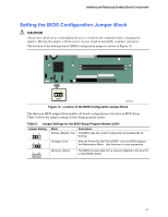
Installing and Replacing Desktop Board Components Connecting Hardware Control and Power Cables Figure 13 shows the location of the chassis intrusion and fan headers and power connectors. Chassis rear fan 1 J6B1 12 V Processor core voltage 1 2 Processor fan 1 J2F1 Chassis intrusion 1 J7H1 Chassis front fan 1 J7H2 Main power 2 1 OM16360 Figure 13. Location of Hardware Control Headers and Power Connectors 39
-
 1
1 -
2
-
3
-
4
-
5
-
6
-
7
-
8
-
9
-
10
-
11
-
12
-
13
-
14
-
15
-
16
-
17
-
18
-
19
-
20
-
21
-
22
-
23
-
24
-
25
-
26
-
27
-
28
-
29
-
30
-
31
-
32
-
33
-
 34
34 -
 35
35 -
 36
36 -
 37
37 -
 38
38 -
 39
39 -
 40
40 -
 41
41 -
 42
42 -
 43
43 -
 44
44 -
45
-
46
-
47
-
48
-
49
-
50
-
51
-
52
-
53
-
54
-
55
-
56
-
57
-
58
-
59
-
60
-
61
-
62
-
63
-
64
-
65
-
66
-
67
-
68
-
69
-
70
-
71
-
72
-
73
-
74
-
75
-
76
-
77
-
78
-
79
-
80
-
81
-
82
-
83
-
84
-
85
-
86
-
87
-
88
 |
 |

Installing and Replacing Desktop Board Components
Connecting Hardware Control and Power Cables
Figure 13 shows the location of the chassis intrusion and fan headers and power connectors.
OM16360
Processor
fan
Chassis
front fan
1
12 V
Processor core
voltage
Main power
Chassis
rear fan
1
J6B1
1
J2F1
J7H2
1
2
1
2
1
J7H1
Chassis intrusion
Figure 13.
Location of Hardware Control Headers and Power Connectors
39