Intel D848PMB Product Guide - Page 35
Connecting Internal Headers, Internal Headers
 |
View all Intel D848PMB manuals
Add to My Manuals
Save this manual to your list of manuals |
Page 35 highlights
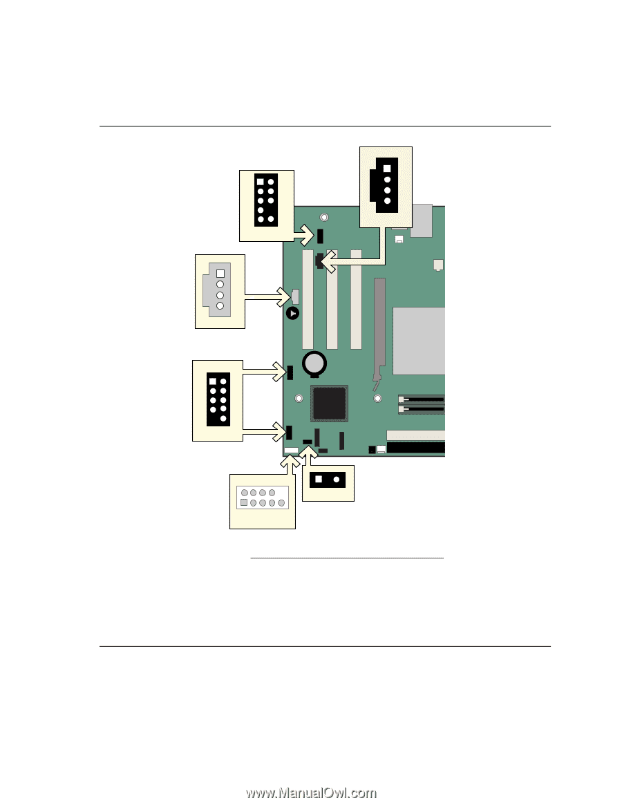
Installing and Replacing Desktop Board Components Connecting Internal Headers Figure 11 shows the location of internal headers. B 1 2 3 4 5 6 7 9 10 J8A1 C A 1 2 3 4 J8B2 J9C2 D J9F1 1 2 3 4 5 6 7 8 10 J9H1 E 2468 1357 9 J9H3 12 F Item A B C D E F Description CD-ROM audio Front panel audio Auxiliary line-in USB 2.0 Front panel Alternate power/sleep LED Figure 11. Internal Headers OM16362 35
-
 1
1 -
2
-
3
-
4
-
5
-
6
-
7
-
8
-
9
-
10
-
11
-
12
-
13
-
14
-
15
-
16
-
17
-
18
-
19
-
20
-
21
-
22
-
23
-
24
-
25
-
26
-
27
-
28
-
29
-
 30
30 -
 31
31 -
 32
32 -
 33
33 -
 34
34 -
 35
35 -
 36
36 -
 37
37 -
 38
38 -
 39
39 -
 40
40 -
41
-
42
-
43
-
44
-
45
-
46
-
47
-
48
-
49
-
50
-
51
-
52
-
53
-
54
-
55
-
56
-
57
-
58
-
59
-
60
-
61
-
62
-
63
-
64
-
65
-
66
-
67
-
68
-
69
-
70
-
71
-
72
-
73
-
74
-
75
-
76
-
77
-
78
-
79
-
80
-
81
-
82
-
83
-
84
-
85
-
86
-
87
-
88
 |
 |
Installing and Replacing Desktop Board Components
Connecting Internal Headers
Figure 11 shows the location of internal headers.
OM16362
1
2
D
A
2
1
3
4
5
6
7
10
B
J9F1
8
9
8
7
6
5
4
2
13
J9H3
F
J9H1
J8B2
1
2
3
4
C
2
1
3
4
5
6
7
10
9
J8A1
J9C2
E
Item
Description
A
CD-ROM audio
B
Front panel audio
C
Auxiliary line-in
D
USB 2.0
E
Front panel
F
Alternate power/sleep LED
Figure 11.
Internal Headers
35