Intel D848PMB Product Guide - Page 37
Installing a Front Panel Audio Solution, Table 8., Front Panel Audio Header Signal Names J8A1
 |
View all Intel D848PMB manuals
Add to My Manuals
Save this manual to your list of manuals |
Page 37 highlights
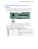
Installing and Replacing Desktop Board Components Installing a Front Panel Audio Solution Figure 11-A shows the location of the front panel audio header. Table 8 shows the pin assignments for the front panel audio header. Table 8. Front Panel Audio Header Signal Names (J8A1) Pin Signal Name 1 AUD-MIC 3 AUD-MIC-BIAS 5 AUD-FPOUT-R 7 HP-ON 9 AUD-FPOUT-L Pin Signal Name 2 AUD-GND 4 AUD-VCC 6 AUD-RET-R 8 KEY 10 AUD-RET-L To install the cable that connects the front panel audio solution to the front panel audio header, follow these steps: 1. Observe the precautions in "Before You Begin" on page 23. 2. Turn off all peripheral devices connected to the computer. Turn off the computer and disconnect the AC power cord. 3. Remove the cover. 4. Locate the front panel audio header. Remove the two jumpers from the header to disable the back panel audio connectors. 5. Install a correctly keyed and shielded front panel audio cable. 6. Connect the audio cable to the front panel audio solution. 7. Replace the cover. To restore back panel operations, follow these steps: 1. Observe the precautions in "Before You Begin" on page 23. 2. Turn off all peripheral devices connected to the computer. Turn off the computer and disconnect the AC power cord. 3. Remove the cover. 4. Remove the front panel audio cable. 5. Install a jumper on pins 5-6 (rear R channel). 6. Install a jumper on pins 9-10 (rear L channel). 7. Replace the cover. NOTE The line out connector, located on the back panel, is designed to power either headphones or amplified speakers only. Poor audio quality may occur if passive (non-amplified) speakers are connected to this output. 37
-
 1
1 -
2
-
3
-
4
-
5
-
6
-
7
-
8
-
9
-
10
-
11
-
12
-
13
-
14
-
15
-
16
-
17
-
18
-
19
-
20
-
21
-
22
-
23
-
24
-
25
-
26
-
27
-
28
-
29
-
30
-
31
-
 32
32 -
 33
33 -
 34
34 -
 35
35 -
 36
36 -
 37
37 -
 38
38 -
 39
39 -
 40
40 -
 41
41 -
 42
42 -
43
-
44
-
45
-
46
-
47
-
48
-
49
-
50
-
51
-
52
-
53
-
54
-
55
-
56
-
57
-
58
-
59
-
60
-
61
-
62
-
63
-
64
-
65
-
66
-
67
-
68
-
69
-
70
-
71
-
72
-
73
-
74
-
75
-
76
-
77
-
78
-
79
-
80
-
81
-
82
-
83
-
84
-
85
-
86
-
87
-
88
 |
 |
