Intel D865GRH D865GRH_ProductGuide01_English. - Page 32
Installing and Removing Memory
 |
View all Intel D865GRH manuals
Add to My Manuals
Save this manual to your list of manuals |
Page 32 highlights
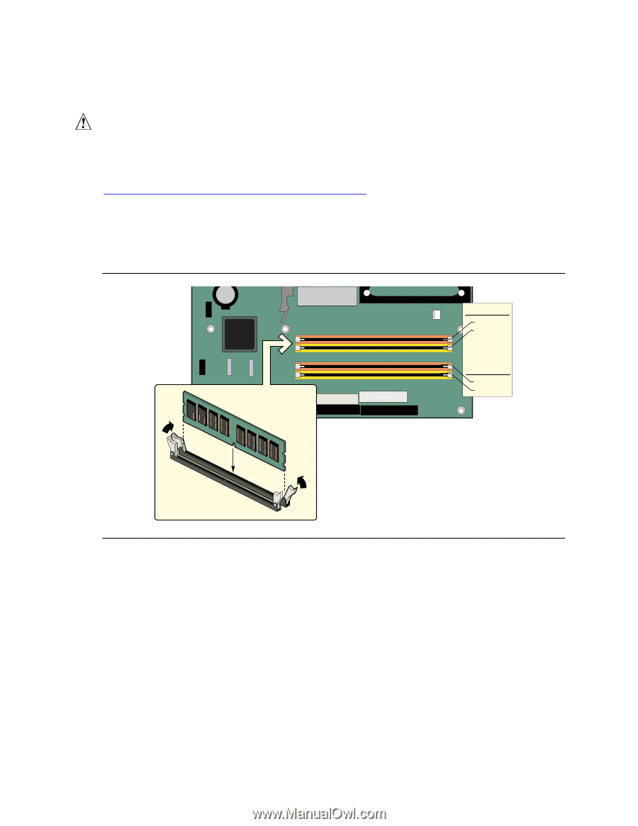
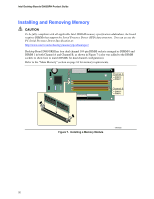
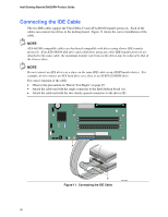
Intel Desktop Boards D865GRH Product Guide Installing and Removing Memory CAUTION To be fully compliant with all applicable Intel SDRAM memory specification addendums, the board requires DIMMs that support the Serial Presence Detect (SPD) data structure. You can access the PC Serial Presence Detect Specification at: http://www.intel.com/technology/memory/pcsdram/spec/ Desktop Board D865GRH has four dual channel 184-pin DIMM sockets arranged as DIMM 0 and DIMM 1 in both Channel A and Channel B, as shown in Figure 7 (color was added to the DIMM sockets to show how to match DIMMs for dual channel configuration). Refer to the "Main Memory" section on page 16 for memory requirements. Channel A DIMM 0 DIMM 1 Channel B DIMM 0 DIMM 1 Figure 7. Installing a Memory Module OM16335 32
-
 1
1 -
2
-
3
-
4
-
5
-
6
-
7
-
8
-
9
-
10
-
11
-
12
-
13
-
14
-
15
-
16
-
17
-
18
-
19
-
20
-
21
-
22
-
23
-
24
-
25
-
26
-
 27
27 -
 28
28 -
 29
29 -
 30
30 -
 31
31 -
 32
32 -
 33
33 -
 34
34 -
 35
35 -
 36
36 -
 37
37 -
38
-
39
-
40
-
41
-
42
-
43
-
44
-
45
-
46
-
47
-
48
-
49
-
50
-
51
-
52
-
53
-
54
-
55
-
56
-
57
-
58
-
59
-
60
-
61
-
62
-
63
-
64
-
65
-
66
-
67
-
68
-
69
-
70
-
71
-
72
-
73
-
74
-
75
-
76
-
77
-
78
-
79
-
80
-
81
-
82
-
83
-
84
-
85
-
86
-
87
-
88
-
89
-
90
-
91
-
92
-
93
-
94
-
95
-
96
-
97
-
98
-
99
-
100
-
101
-
102
 |
 |