Intel D865GRH D865GRH_ProductGuide01_English. - Page 42
Connecting Hardware Control and Power Cables,
 |
View all Intel D865GRH manuals
Add to My Manuals
Save this manual to your list of manuals |
Page 42 highlights
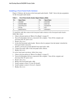
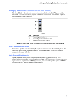
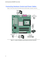
Intel Desktop Boards D865GRH Product Guide Connecting Hardware Control and Power Cables Figure 15 shows the location of the chassis intrusion and fan headers, and power connectors. Chassis rear fan 1 J6B1 12 V processor core voltage connector 1 2 Processor fan 1 J6B1 Chassis intrusion connector 1 J9H2 Chassis front fan 1 J7J3 Main power connector 2 1 OM16339 Figure 15. Location of Hardware Control Headers and Power Connectors 42
-
 1
1 -
2
-
3
-
4
-
5
-
6
-
7
-
8
-
9
-
10
-
11
-
12
-
13
-
14
-
15
-
16
-
17
-
18
-
19
-
20
-
21
-
22
-
23
-
24
-
25
-
26
-
27
-
28
-
29
-
30
-
31
-
32
-
33
-
34
-
35
-
36
-
 37
37 -
 38
38 -
 39
39 -
 40
40 -
 41
41 -
 42
42 -
 43
43 -
 44
44 -
 45
45 -
 46
46 -
 47
47 -
48
-
49
-
50
-
51
-
52
-
53
-
54
-
55
-
56
-
57
-
58
-
59
-
60
-
61
-
62
-
63
-
64
-
65
-
66
-
67
-
68
-
69
-
70
-
71
-
72
-
73
-
74
-
75
-
76
-
77
-
78
-
79
-
80
-
81
-
82
-
83
-
84
-
85
-
86
-
87
-
88
-
89
-
90
-
91
-
92
-
93
-
94
-
95
-
96
-
97
-
98
-
99
-
100
-
101
-
102
 |
 |

Intel Desktop Boards D865GRH Product Guide
42
Connecting Hardware Control and Power Cables
Figure 15 shows the location of the chassis intrusion and fan headers, and power connectors.
OM16339
Processor
fan
1
Chassis
front fan
1
Chassis
rear fan
1
12 V
processor core
voltage connector
1
Main power
connector
1
J6B1
J6B1
J7J3
2
2
Chassis intrusion
1
J9H2
connector
Figure 15.
Location of Hardware Control Headers and Power Connectors