Intel D915GMH English Manual Product Guide - Page 38
Installing and Removing a PCI Express x16 Card, Removing the PCI Express x16 Card
 |
View all Intel D915GMH manuals
Add to My Manuals
Save this manual to your list of manuals |
Page 38 highlights
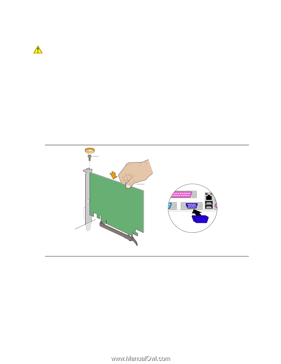
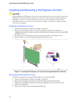
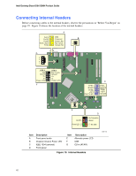
Intel Desktop Board D915GMH Product Guide Installing and Removing a PCI Express x16 Card CAUTION When installing any PCI Express x16 card on the desktop board, ensure that it is fully seated in the PCI Express x16 connector before you power on the system. If the card is not fully seated in the PCI Express connector, an electrical short may result across the PCI Express connector pins. Depending on the over-current protection of the power supply, certain board components and/or traces may be damaged. Installing a PCI Express x16 Card 1. Observe the precautions in "Before You Begin" on page 25. 2. Place the card in the PCI Express x16 connector and press down on the card until it is completely seated in the connector and the card retention notch snaps into place around the RM pin (Figure 16, A). 3. Secure the card's metal bracket to the chassis back panel with a screw (Figure 16, B). 4. Place the VGA cover over the back panel VGA port (Figure 16, C). B A C OM17230 Figure 16. Inserting the PCI Express x16 Card and Covering the Back Panel VGA Port Removing the PCI Express x16 Card Follow these instructions to remove the PCI Express x16 card from the RM: 1. Observe the precautions in "Before You Begin" on page 25. 2. Remove the screw that secures the card's metal bracket to the chassis back panel. 3. Push back on the RM lever until the retention pin completely clears the notch in the card. 4. Pull the card straight up. 5. Remove the VGA cover from the back panel VGA port. 38
-
 1
1 -
2
-
3
-
4
-
5
-
6
-
7
-
8
-
9
-
10
-
11
-
12
-
13
-
14
-
15
-
16
-
17
-
18
-
19
-
20
-
21
-
22
-
23
-
24
-
25
-
26
-
27
-
28
-
29
-
30
-
31
-
32
-
 33
33 -
 34
34 -
 35
35 -
 36
36 -
 37
37 -
 38
38 -
 39
39 -
 40
40 -
 41
41 -
 42
42 -
 43
43 -
44
-
45
-
46
-
47
-
48
-
49
-
50
-
51
-
52
-
53
-
54
-
55
-
56
-
57
-
58
-
59
-
60
-
61
-
62
-
63
-
64
-
65
-
66
-
67
-
68
-
69
-
70
-
71
-
72
-
73
-
74
-
75
-
76
-
77
-
78
-
79
-
80
 |
 |