Intel D915GMH English Manual Product Guide - Page 42
Connecting Internal Headers, Internal Headers
 |
View all Intel D915GMH manuals
Add to My Manuals
Save this manual to your list of manuals |
Page 42 highlights
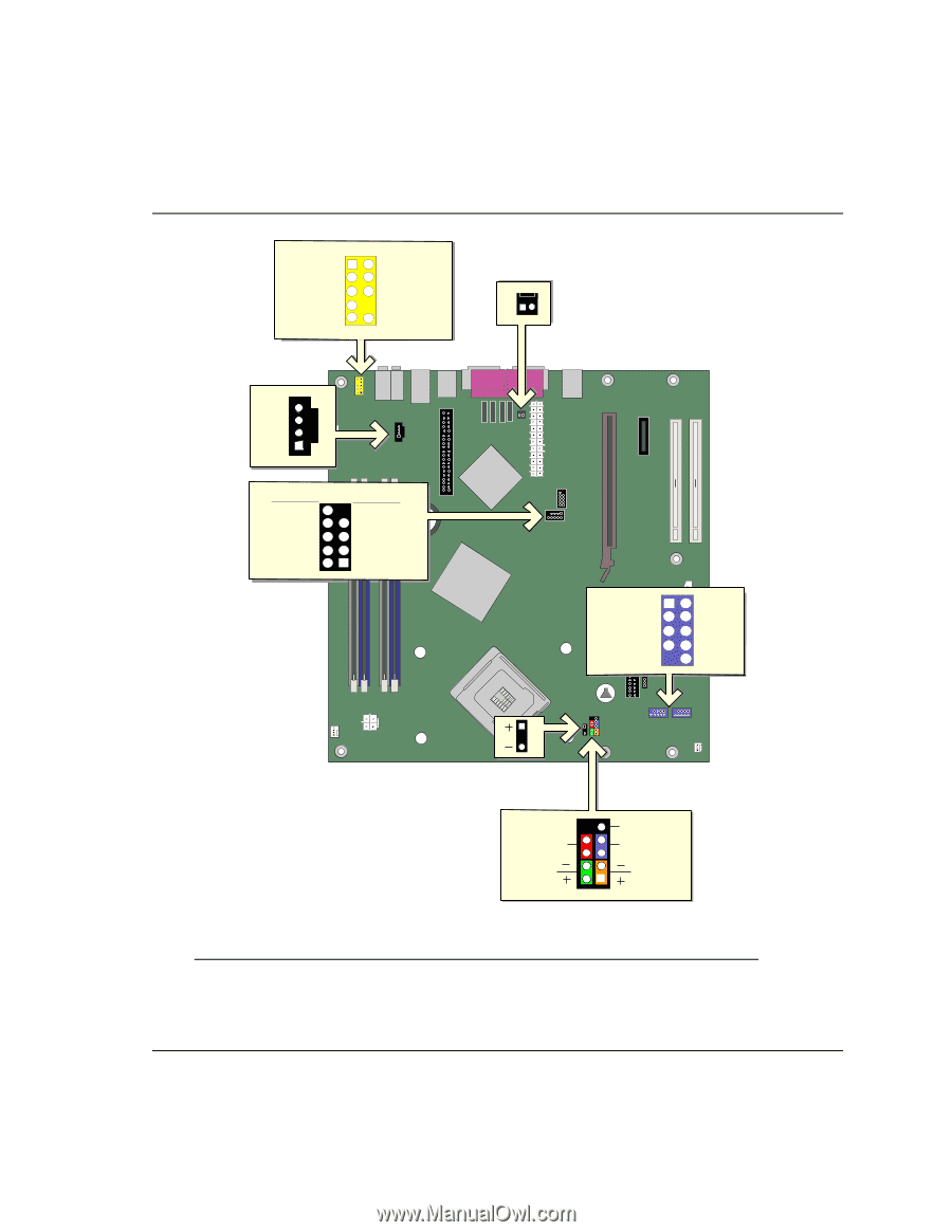
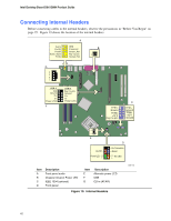
Intel Desktop Board D915GMH Product Guide Connecting Internal Headers Before connecting cables to the internal headers, observe the precautions in "Before You Begin" on page 25. Figure 19 shows the location of the internal headers. A Port1L 1 2 Port1R 3 4 Port2R 5 6 Sense_Send 7 Port2L 9 10 GND Presence# Sense1_Ret Key (no pin) Sense2_Ret B 1 G 4 3 2 1 USB A USB B N/C 10 Key (no pin) Ground 8 7 Ground D+ 6 5 D+ D- 4 3 DPower (+5V) 2 1 Power (+5V) F C TPA1+ 1 2 TPA1Ground 3 4 Ground TPA2+ 5 6 TPA2- +12 V 7 8 +12 V Key (no pin) 10 Ground 1 3 E D On/Off Power LED 9 87 65 43 21 No Connection Reset HD LED Item A B C D Description Front panel audio Chassis intrusion Power LED IEEE 1394 (optional) Front panel Item E F G Description Alternate power LED USB CD-in (ATAPI) Figure 19. Internal Headers OM17180 42
-
 1
1 -
2
-
3
-
4
-
5
-
6
-
7
-
8
-
9
-
10
-
11
-
12
-
13
-
14
-
15
-
16
-
17
-
18
-
19
-
20
-
21
-
22
-
23
-
24
-
25
-
26
-
27
-
28
-
29
-
30
-
31
-
32
-
33
-
34
-
35
-
36
-
 37
37 -
 38
38 -
 39
39 -
 40
40 -
 41
41 -
 42
42 -
 43
43 -
 44
44 -
 45
45 -
 46
46 -
 47
47 -
48
-
49
-
50
-
51
-
52
-
53
-
54
-
55
-
56
-
57
-
58
-
59
-
60
-
61
-
62
-
63
-
64
-
65
-
66
-
67
-
68
-
69
-
70
-
71
-
72
-
73
-
74
-
75
-
76
-
77
-
78
-
79
-
80
 |
 |