Contents
vii
Trusted Platform Module Ownership
.....................................................................................
65
Enabling the Trusted Platform Module
..................................................................................
66
Assuming Trusted Platform Module Ownership
....................................................................
66
Recovery Procedures
............................................................................................................
67
Clearing Trusted Platform Module Ownership
......................................................................
69
Software Support
..................................................................................................................
69
5
Desktop Board Resources
Memory Map
.........................................................................................................................
71
DMA Channels
......................................................................................................................
71
Interrupts
...............................................................................................................................
72
A
Error Messages and Indicators
BIOS Beep Codes
.................................................................................................................
73
BIOS Error Messages
...........................................................................................................
74
B
Regulatory Compliance
Safety Regulations
................................................................................................................
77
European Union Declaration of Conformity Statement
.........................................................
77
Product Ecology Statements
.................................................................................................
78
EMC Regulations
..................................................................................................................
79
Product Certification Markings (Board Level)
........................................................................
80
Figures
1.
Desktop Board D915GMH Components
........................................................................
12
2.
Location of Standby Power Indicator
..............................................................................
22
3.
Installing the I/O Shield
...................................................................................................
28
4.
Desktop Board D915GMH Mounting Screw Hole Locations
..........................................
29
5.
Lift Socket Lever
.............................................................................................................
30
6.
Lift the Load Plate and Don’t Touch the Socket Contacts
..............................................
30
7.
Remove the Protective Socket Cover
.............................................................................
31
8.
Remove the Processor from the Protective Processor Cover/Do Not Touch
.................
31
9.
Install Processor
.............................................................................................................
32
10. Close the Load Plate
......................................................................................................
32
11. Connecting the Processor Fan Heat Sink Cable to the Processor Fan Connector
........
33
12. Dual Configuration Example 1
........................................................................................
34
13. Dual Configuration Example 2
........................................................................................
35
14. Dual Configuration Example 3
........................................................................................
35
15. Installing a DIMM
............................................................................................................
36
16. Inserting the PCI Express x16 Card and Covering the Back Panel VGA Port
...............
38
17. Connecting the IDE Cable
..............................................................................................
39
18. Connecting the Serial ATA Cable
...................................................................................
40
19. Internal Headers
.............................................................................................................
42
20. Back Panel Audio Connectors
........................................................................................
45
21. Fan Header Locations
....................................................................................................
46
22. Connecting 2x10 Power Supply Cables
.........................................................................
47
23. Connecting 2x12 Power Supply Cables
.........................................................................
48
24. Location of Other Connectors
.........................................................................................
49
25. Location of the BIOS Configuration Jumper Block
.........................................................
50

 1
1 2
2 3
3 4
4 5
5 6
6 7
7 8
8 9
9 10
10 11
11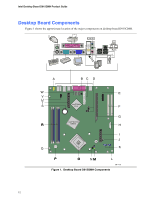 12
12

