Intel D915GVWB Product Specification - Page 33
Wake-up Devices and Events
 |
View all Intel D915GVWB manuals
Add to My Manuals
Save this manual to your list of manuals |
Page 33 highlights
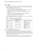
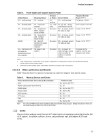
Product Description Table 8. Power States and Targeted System Power Global States Sleeping States Process or States Device States Targeted System Power (Note 1) G0 - working state S0 - working C0 - working D0 - working state. Full power > 30 W G1 - sleeping state G1 - sleeping state S1 - Processor stopped S3 - Suspend to RAM. Context saved to RAM. C1 - stop grant No power D1, D2, D3 - device specification specific. D3 - no power except for wake-up logic. 5 W < power < 52.5 W Power < 5 W (Note 2) G1 - sleeping state S4 - Suspend to disk. Context saved to disk. No power D3 - no power except Power < 5 W (Note 2) for wake-up logic. G2/S5 S5 - Soft off. Context not saved. Cold boot is required. No power D3 - no power except for wake-up logic. Power < 5 W (Note 2) G3 - mechanical off AC power is disconnected from the computer. No power to the system. No power D3 - no power for wake-up logic, except when provided by battery or external source. No power to the system. Service can be performed safely. Notes: 1. Total system power is dependent on the system configuration, including add-in boards and peripherals powered by the system chassis' power supply. 2. Dependent on the standby power consumption of wake-up devices used in the system. 1.12.1.2 Wake-up Devices and Events Table 9 lists the devices or specific events that can wake the computer from specific states. Table 9. Wake-up Devices and Events These devices/events can wake up the computer... LAN Modem (back panel Serial Port A) PME# signal Power switch PS/2 devices RTC alarm USB WAKE# ...from this state S1, S3, S4, S5 (Note) S1, S3 S1, S3, S4, S5 (Note) S1, S3, S4, S5 S1, S3 S1, S3, S4, S5 S1, S3 S1, S3, S4, S5 Note: For LAN and PME# signal, S5 is disabled by default in the BIOS Setup program. Setting this option to Power On will enable a wake-up event from LAN in the S5 state. NOTE The use of these wake-up events from an ACPI state requires an operating system that provides full ACPI support. In addition, software, drivers, and peripherals must fully support ACPI wake events. 33
-
 1
1 -
2
-
3
-
4
-
5
-
6
-
7
-
8
-
9
-
10
-
11
-
12
-
13
-
14
-
15
-
16
-
17
-
18
-
19
-
20
-
21
-
22
-
23
-
24
-
25
-
26
-
27
-
 28
28 -
 29
29 -
 30
30 -
 31
31 -
 32
32 -
 33
33 -
 34
34 -
 35
35 -
 36
36 -
 37
37 -
 38
38 -
39
-
40
-
41
-
42
-
43
-
44
-
45
-
46
-
47
-
48
-
49
-
50
-
51
-
52
-
53
-
54
-
55
-
56
-
57
-
58
-
59
-
60
-
61
-
62
-
63
-
64
-
65
-
66
-
67
-
68
-
69
-
70
-
71
-
72
-
73
-
74
-
75
-
76
-
77
-
78
-
79
-
80
-
81
-
82
-
83
-
84
 |
 |