Intel D915GVWB Product Specification - Page 8

Front Chassis Fan and Rear Chassis Fan Connectors

Page 8 highlights

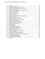
Intel Desktop Board D915GVWB Technical Product Specification 14. Interrupts ...44 15. PCI Interrupt Routing Map 45 16. Back Panel Connectors Shown in Figure 15 47 17. Component-side Connectors Shown in Figure 16 49 18. Front Panel Audio Connector 49 19. Front Chassis Fan and Rear Chassis Fan Connectors 50 20. Processor Fan Connector 50 21. Chassis Intrusion Connector 50 22. Serial ATA Connectors 50 23. Main Power Connector 51 24. ATX12V Power Connector 51 25. Auxiliary Front Panel Power/Sleep LED Connector 52 26. Front Panel Connector 52 27. States for a One-Color Power LED 53 28. States for a Two-Color Power LED 53 29. BIOS Setup Configuration Jumper Settings 55 30. DC Loading Characteristics 58 31. Fan Connector Current Capability 58 32. Thermal Considerations for Components 62 33. Environmental Specifications 63 34. Safety Regulations ...64 35. EMC Regulations ...64 36. Product Certification Markings 67 37. BIOS Setup Program Menu Bar 70 38. BIOS Setup Program Function Keys 70 39. Boot Device Menu Options 73 40. Supervisor and User Password Functions 75 41. BIOS Error Messages 77 42. Uncompressed INIT Code Checkpoints 79 43. Boot Block Recovery Code Checkpoints 79 44. Runtime Code Uncompressed in F000 Shadow RAM 80 45. Bus Initialization Checkpoints 83 46. Upper Nibble High Byte Functions 83 47. Lower Nibble High Byte Functions 84 48. Beep Codes ...84 viii

  • 1
  • 2
  • 3
  • 4
  • 5
  • 6
  • 7
  • 8
  • 9
  • 10
  • 11
  • 12
  • 13
  • 14
  • 15
  • 16
  • 17
  • 18
  • 19
  • 20
  • 21
  • 22
  • 23
  • 24
  • 25
  • 26
  • 27
  • 28
  • 29
  • 30
  • 31
  • 32
  • 33
  • 34
  • 35
  • 36
  • 37
  • 38
  • 39
  • 40
  • 41
  • 42
  • 43
  • 44
  • 45
  • 46
  • 47
  • 48
  • 49
  • 50
  • 51
  • 52
  • 53
  • 54
  • 55
  • 56
  • 57
  • 58
  • 59
  • 60
  • 61
  • 62
  • 63
  • 64
  • 65
  • 66
  • 67
  • 68
  • 69
  • 70
  • 71
  • 72
  • 73
  • 74
  • 75
  • 76
  • 77
  • 78
  • 79
  • 80
  • 81
  • 82
  • 83
  • 84

Intel Desktop Board D915GVWB Technical Product Specification
viii
14.
Interrupts
......................................................................................................................
44
15.
PCI Interrupt Routing Map
...........................................................................................
45
16.
Back Panel Connectors Shown in Figure 15
................................................................
47
17.
Component-side Connectors Shown in Figure 16
.......................................................
49
18.
Front Panel Audio Connector
.......................................................................................
49
19.
Front Chassis Fan and Rear Chassis Fan Connectors
................................................
50
20.
Processor Fan Connector
............................................................................................
50
21.
Chassis Intrusion Connector
........................................................................................
50
22.
Serial ATA Connectors
.................................................................................................
50
23.
Main Power Connector
.................................................................................................
51
24.
ATX12V Power Connector
...........................................................................................
51
25.
Auxiliary Front Panel Power/Sleep LED Connector
.....................................................
52
26.
Front Panel Connector
.................................................................................................
52
27.
States for a One-Color Power LED
..............................................................................
53
28.
States for a Two-Color Power LED
..............................................................................
53
29.
BIOS Setup Configuration Jumper Settings
.................................................................
55
30.
DC Loading Characteristics
.........................................................................................
58
31.
Fan Connector Current Capability
................................................................................
58
32.
Thermal Considerations for Components
....................................................................
62
33.
Environmental Specifications
.......................................................................................
63
34.
Safety Regulations
.......................................................................................................
64
35.
EMC Regulations
.........................................................................................................
64
36.
Product Certification Markings
.....................................................................................
67
37.
BIOS Setup Program Menu Bar
...................................................................................
70
38.
BIOS Setup Program Function Keys
............................................................................
70
39.
Boot Device Menu Options
..........................................................................................
73
40.
Supervisor and User Password Functions
...................................................................
75
41.
BIOS Error Messages
..................................................................................................
77
42.
Uncompressed INIT Code Checkpoints
.......................................................................
79
43.
Boot Block Recovery Code Checkpoints
.....................................................................
79
44.
Runtime Code Uncompressed in F000 Shadow RAM
.................................................
80
45.
Bus Initialization Checkpoints
......................................................................................
83
46.
Upper Nibble High Byte Functions
...............................................................................
83
47.
Lower Nibble High Byte Functions
...............................................................................
84
48.
Beep Codes
.................................................................................................................
84