Intel D915GVWB Product Specification - Page 36
V Standby Power Indicator LED
 |
View all Intel D915GVWB manuals
Add to My Manuals
Save this manual to your list of manuals |
Page 36 highlights
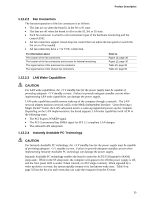
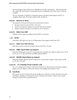
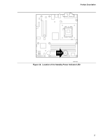
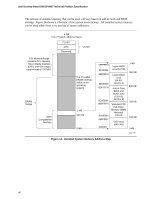
Intel Desktop Board D915GVWB Technical Product Specification The board supports the PCI Bus Power Management Interface Specification. Add-in boards that also support this specification can participate in power management and can be used to wake the computer. The use of Instantly Available PC technology requires operating system support and PCI 2.2 compliant add-in cards, PCI Express add-in cards, and drivers. 1.12.2.5 Resume on Ring The operation of Resume on Ring can be summarized as follows: • Resumes operation from ACPI S1 or S3 states • Detects incoming call similarly for external and internal modems • Requires modem interrupt be unmasked for correct operation 1.12.2.6 Wake from USB USB bus activity wakes the computer from ACPI S1 or S3 states. NOTE Wake from USB requires the use of a USB peripheral that supports Wake from USB. 1.12.2.7 Wake from PS/2 Devices PS/2 device activity wakes the computer from an ACPI S1 or S3 state. 1.12.2.8 PME# Signal Wake-up Support When the PME# signal on the PCI Conventional bus is asserted, the computer wakes from an ACPI S1, S3, S4, or S5 state (with Wake on PME enabled in BIOS). 1.12.2.9 WAKE# Signal Wake-up Support When the WAKE# signal on the PCI Express bus is asserted, the computer wakes from an ACPI S1, S3, S4, or S5 state. 1.12.2.10 +5 V Standby Power Indicator LED The +5 V standby power indicator LED shows that power is still present even when the computer appears to be off. Figure 13 shows the location of the standby power indicator LED. CAUTION If AC power has been switched off and the standby power indicator is still lit, disconnect the power cord before installing or removing any devices connected to the board. Failure to do so could damage the board and any attached devices. 36
-
 1
1 -
2
-
3
-
4
-
5
-
6
-
7
-
8
-
9
-
10
-
11
-
12
-
13
-
14
-
15
-
16
-
17
-
18
-
19
-
20
-
21
-
22
-
23
-
24
-
25
-
26
-
27
-
28
-
29
-
30
-
 31
31 -
 32
32 -
 33
33 -
 34
34 -
 35
35 -
 36
36 -
 37
37 -
 38
38 -
 39
39 -
 40
40 -
 41
41 -
42
-
43
-
44
-
45
-
46
-
47
-
48
-
49
-
50
-
51
-
52
-
53
-
54
-
55
-
56
-
57
-
58
-
59
-
60
-
61
-
62
-
63
-
64
-
65
-
66
-
67
-
68
-
69
-
70
-
71
-
72
-
73
-
74
-
75
-
76
-
77
-
78
-
79
-
80
-
81
-
82
-
83
-
84
 |
 |