Intel D915GVWB Product Specification - Page 43
PCI Configuration Space Map
 |
View all Intel D915GVWB manuals
Add to My Manuals
Save this manual to your list of manuals |
Page 43 highlights
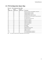
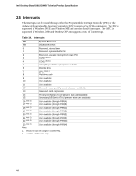
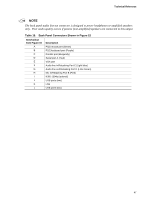
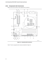
Technical Reference 2.5 PCI Configuration Space Map Table 13. PCI Configuration Space Map Bus Number (hex) 00 00 00 00 00 00 00 00 00 00 00 00 00 00 00 00 00 (Note) (Note) Device Number (hex) 00 02 02 1B 1C 1C 1C 1D 1D 1D 1D 1D 1E 1F 1F 1F 1F 00 01 Function Number (hex) 00 00 01 00 00 01 03 00 01 02 03 07 00 00 01 02 03 00 00 Description Memory controller of Intel 82915GV component Integrated graphics controller Integrated graphics controller Intel High Definition Audio Controller PCI Express port 1 (PCI Express x1 bus connector 1) PCI Express port 2 PCI Express port 4 (not used) USB UHCI controller 1 USB UHCI controller 2 USB UHCI controller 3 USB UHCI controller 4 EHCI controller PCI bridge PCI controller Parallel ATA IDE controller Serial ATA controller SMBus controller PCI Conventional bus connector 1 PCI Conventional bus connector 2 Note: Bus number is dynamic and can change based on add-in cards used. 43
-
 1
1 -
2
-
3
-
4
-
5
-
6
-
7
-
8
-
9
-
10
-
11
-
12
-
13
-
14
-
15
-
16
-
17
-
18
-
19
-
20
-
21
-
22
-
23
-
24
-
25
-
26
-
27
-
28
-
29
-
30
-
31
-
32
-
33
-
34
-
35
-
36
-
37
-
 38
38 -
 39
39 -
 40
40 -
 41
41 -
 42
42 -
 43
43 -
 44
44 -
 45
45 -
 46
46 -
 47
47 -
 48
48 -
49
-
50
-
51
-
52
-
53
-
54
-
55
-
56
-
57
-
58
-
59
-
60
-
61
-
62
-
63
-
64
-
65
-
66
-
67
-
68
-
69
-
70
-
71
-
72
-
73
-
74
-
75
-
76
-
77
-
78
-
79
-
80
-
81
-
82
-
83
-
84
 |
 |