Intel D915GVWB Product Specification - Page 35
Fan Connectors, 12.2.3, LAN Wake Capabilities, CAUTION, 12.2.4, Instantly Available PC
 |
View all Intel D915GVWB manuals
Add to My Manuals
Save this manual to your list of manuals |
Page 35 highlights
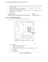
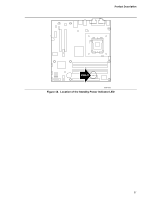
Product Description 1.12.2.2 Fan Connectors The function/operation of the fan connectors is as follows: • The fans are on when the board is in the S0 or S1 state. • The fans are off when the board is off or in the S3, S4, or S5 state. • Each fan connector is wired to a fan tachometer input of the hardware monitoring and fan control ASIC. • All fan connectors support closed-loop fan control that can adjust the fan speed or switch the fan on or off as needed. • All fan connectors have a +12 V DC connection. For information about The location of the fan connectors The location of the fan connectors and sensors for thermal monitoring The signal names of the processor fan connector The signal names of the chassis fan connectors Refer to Figure 16, page 48 Figure 12, page 30 Table 20, page 50 Table 19, page 50 1.12.2.3 LAN Wake Capabilities CAUTION For LAN wake capabilities, the +5 V standby line for the power supply must be capable of providing adequate +5 V standby current. Failure to provide adequate standby current when implementing LAN wake capabilities can damage the power supply. LAN wake capabilities enable remote wake-up of the computer through a network. The LAN network adapter monitors network traffic at the Media Independent Interface. Upon detecting a Magic Packet* frame, the LAN subsystem asserts a wake-up signal that powers up the computer. Depending on the LAN implementation, the board supports LAN wake capabilities with ACPI in the following ways: • The PCI Express WAKE# signal • The PCI Conventional bus PME# signal for PCI 2.2 compliant LAN designs • The onboard LAN subsystem 1.12.2.4 Instantly Available PC Technology CAUTION For Instantly Available PC technology, the +5 V standby line for the power supply must be capable of providing adequate +5 V standby current. Failure to provide adequate standby current when implementing Instantly Available PC technology can damage the power supply. Instantly Available PC technology enables the board to enter the ACPI S3 (Suspend-to-RAM) sleep-state. While in the S3 sleep-state, the computer will appear to be off (the power supply is off, and the front panel LED is amber if dual colored, or off if single colored.) When signaled by a wake-up device or event, the system quickly returns to its last known wake state. Table 9 on page 33 lists the devices and events that can wake the computer from the S3 state. 35
-
 1
1 -
2
-
3
-
4
-
5
-
6
-
7
-
8
-
9
-
10
-
11
-
12
-
13
-
14
-
15
-
16
-
17
-
18
-
19
-
20
-
21
-
22
-
23
-
24
-
25
-
26
-
27
-
28
-
29
-
 30
30 -
 31
31 -
 32
32 -
 33
33 -
 34
34 -
 35
35 -
 36
36 -
 37
37 -
 38
38 -
 39
39 -
 40
40 -
41
-
42
-
43
-
44
-
45
-
46
-
47
-
48
-
49
-
50
-
51
-
52
-
53
-
54
-
55
-
56
-
57
-
58
-
59
-
60
-
61
-
62
-
63
-
64
-
65
-
66
-
67
-
68
-
69
-
70
-
71
-
72
-
73
-
74
-
75
-
76
-
77
-
78
-
79
-
80
-
81
-
82
-
83
-
84
 |
 |