Intel D945GCCR Product Specification - Page 52
Integrator's Note
 |
View all Intel D945GCCR manuals
Add to My Manuals
Save this manual to your list of manuals |
Page 52 highlights
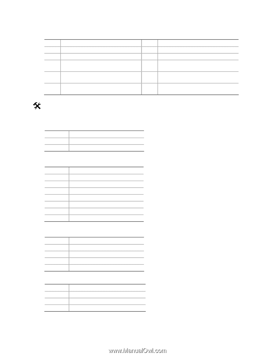
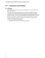
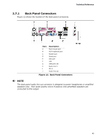
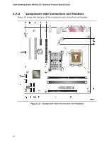
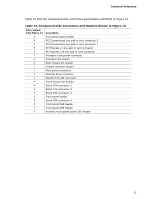
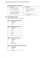
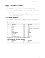
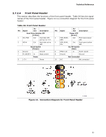
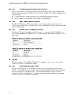
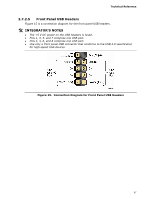
Intel Desktop Board D945GCCR Technical Product Specification Table 16. Front Panel Audio Header Pin Signal Name 1 Port E [Port 1] Left Channel 3 Port E [Port 1] Right Channel 5 Port F [Port 2] Right Channel 7 Port E [Port 1] and Port F [Port 2] Sense send (jack detection) 9 Port F [Port 2] Left Channel Pin Signal Name 2 Ground 4 Presence# (dongle present) 6 Port E [Port 1] Sense return (jack detection) 8 Key 10 Port F [Port 2] Sense return (jack detection) # INTEGRATOR'S NOTE The front panel audio header is colored yellow. Table 17. Chassis Intrusion Header Pin Signal Name 1 Intruder 2 Ground Table 18. Serial ATA Connectors Pin Signal Name 1 Ground 2 TXP 3 TXN 4 Ground 5 RXN 6 RXP 7 Ground Table 19. Processor Fan Header Pin Signal Name 1 Ground 2 +12 V 3 FAN_TACH 4 FAN_CONTROL Table 20. Front and Rear Chassis Fan Headers Pin Signal Name 1 FAN_CONTROL 2 +12 V 3 FAN_TACH 52
-
 1
1 -
2
-
3
-
4
-
5
-
6
-
7
-
8
-
9
-
10
-
11
-
12
-
13
-
14
-
15
-
16
-
17
-
18
-
19
-
20
-
21
-
22
-
23
-
24
-
25
-
26
-
27
-
28
-
29
-
30
-
31
-
32
-
33
-
34
-
35
-
36
-
37
-
38
-
39
-
40
-
41
-
42
-
43
-
44
-
45
-
46
-
 47
47 -
 48
48 -
 49
49 -
 50
50 -
 51
51 -
 52
52 -
 53
53 -
 54
54 -
 55
55 -
 56
56 -
 57
57 -
58
-
59
-
60
-
61
-
62
-
63
-
64
-
65
-
66
-
67
-
68
-
69
-
70
-
71
-
72
-
73
-
74
-
75
-
76
-
77
-
78
-
79
-
80
-
81
-
82
-
83
-
84
-
85
-
86
-
87
-
88
-
89
-
90
-
91
-
92
-
93
-
94
 |
 |