Intel DG41RQ Product Guide - Page 43
Front Panel Audio Header, S/PDIF Connector, Table 5. Front Panel Audio Signal Names for Intel HD Audio
 |
UPC - 735858206860
View all Intel DG41RQ manuals
Add to My Manuals
Save this manual to your list of manuals |
Page 43 highlights
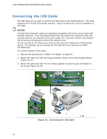
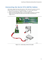
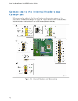
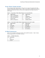
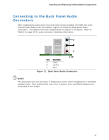
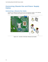
Installing and Replacing Desktop Board Components Front Panel Audio Header The front panel audio header shown in Figure 20, A on page 42 supports both High Definition (HD) Audio and AC'97 Audio. Table 5 shows the pin assignments and signal names for HD Audio and Table 6 shows the pin assignments and signal names for AC'97 Audio. Table 5. Front Panel Audio Signal Names for Intel HD Audio Pin Signal Name 1 PORT 1L (Microphone) 3 PORT 1R (Microphone) 5 PORT 2R (Headphone) 7 SENSE_SEND 9 PORT 2L (Headphone) Pin Signal Name 2 GND 4 PRESENCE# 6 SENSE1_RETURN 8 KEY (no pin) 10 SENSE2_RETURN Table 6. Front Panel Audio Header Signal Names for AC'97 Audio Pin Signal Name 1 MIC Pin Signal Name 2 AUD_GND 3 MIC_BIAS 4 AUD_GND 5 FP_OUT_R 7 AUD_5V 9 FP_OUT_L 6 FP_RETURN_R 8 KEY (no pin) 10 FP_RETURN_L S/PDIF Connector Figure 20, B on page 42 shows the location of the S/PDIF connector. Table 7 shows the pin assignments for the S/PDIF connector. Table 7. S/PDIF Connector Pin Description 1 VCC 2 SPDIF OUT 3 Ground 43
-
 1
1 -
2
-
3
-
4
-
5
-
6
-
7
-
8
-
9
-
10
-
11
-
12
-
13
-
14
-
15
-
16
-
17
-
18
-
19
-
20
-
21
-
22
-
23
-
24
-
25
-
26
-
27
-
28
-
29
-
30
-
31
-
32
-
33
-
34
-
35
-
36
-
37
-
 38
38 -
 39
39 -
 40
40 -
 41
41 -
 42
42 -
 43
43 -
 44
44 -
 45
45 -
 46
46 -
 47
47 -
 48
48 -
49
-
50
-
51
-
52
-
53
-
54
-
55
-
56
-
57
-
58
-
59
-
60
-
61
-
62
-
63
-
64
-
65
-
66
-
67
-
68
-
69
-
70
-
71
-
72
 |
 |
