Intel DG41RQ Product Guide - Page 7
s, Tables, Connecting the Processor Fan Heat Sink Cable to the Processor Fan Header - memory
 |
UPC - 735858206860
View all Intel DG41RQ manuals
Add to My Manuals
Save this manual to your list of manuals |
Page 7 highlights
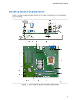
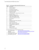
Contents Figures 1. Intel Desktop Board DG41RQ Components 11 2. LAN Connector LEDs 17 3. Location of the Standby Power Indicator 23 4. Installing the I/O Shield 27 5. Intel Desktop Board DG41RQ Mounting Screw Hole Locations 28 6. Lift the Socket Lever 29 7. Lift the Load Plate 30 8. Remove the Protective Socket Cover 30 9. Remove the Processor from the Protective Processor Cover 31 10. Install the Processor 31 11. Close the Load Plate 32 12. Connecting the Processor Fan Heat Sink Cable to the Processor Fan Header ..........33 13. Dual Channel Memory Configuration Example 34 14. Use DDR2 DIMMs 35 15. Installing a DIMM 36 16. Installing a PCI Express x16 Card 38 17. Removing a PCI Express x16 Card 39 18. Connecting the IDE Cable 40 19. Connecting a Serial ATA Cable 41 20. Internal Headers and Connectors 42 21. Back Panel Audio Connectors 47 22. Location of the Rear Chassis Fan Header 48 23. Connecting Power Supply Cables 49 24. Location of the BIOS Configuration Jumper Block 50 25. Removing the Battery 56 Tables 1. Feature Summary 9 2. Intel Desktop Board DG41RQ Components 12 3. Audio Jack Retasking Support 16 4. LAN Connector LEDs 18 5. Front Panel Audio Signal Names for Intel HD Audio 43 6. Front Panel Audio Header Signal Names for AC'97 Audio 43 7. S/PDIF Connector 43 8. Serial Port Header Signal Names 44 9. Parallel Port Header Signal Names 44 10. Front Panel Header 45 11. Alternate Front Panel Power LED Header 45 12. USB 2.0 Header Signal Names 46 13. Jumper Settings for the BIOS Setup Program Modes 50 14. Beep Codes 61 15. BIOS Error Messages 61 16. Safety Standards 63 17. Lead-Free Board Markings 68 18. EMC Regulations 69 19. Product Certification Markings 71 vii
-
 1
1 -
 2
2 -
 3
3 -
 4
4 -
 5
5 -
 6
6 -
 7
7 -
 8
8 -
 9
9 -
 10
10 -
 11
11 -
 12
12 -
13
-
14
-
15
-
16
-
17
-
18
-
19
-
20
-
21
-
22
-
23
-
24
-
25
-
26
-
27
-
28
-
29
-
30
-
31
-
32
-
33
-
34
-
35
-
36
-
37
-
38
-
39
-
40
-
41
-
42
-
43
-
44
-
45
-
46
-
47
-
48
-
49
-
50
-
51
-
52
-
53
-
54
-
55
-
56
-
57
-
58
-
59
-
60
-
61
-
62
-
63
-
64
-
65
-
66
-
67
-
68
-
69
-
70
-
71
-
72
 |
 |