Intel DG965MQ DG965MQ Technical Product Specification - Page 55
Table 23. Parallel Port Header, Table 24. Front and Rear Chassis Fan Headers, Table 25. Processor
 |
View all Intel DG965MQ manuals
Add to My Manuals
Save this manual to your list of manuals |
Page 55 highlights
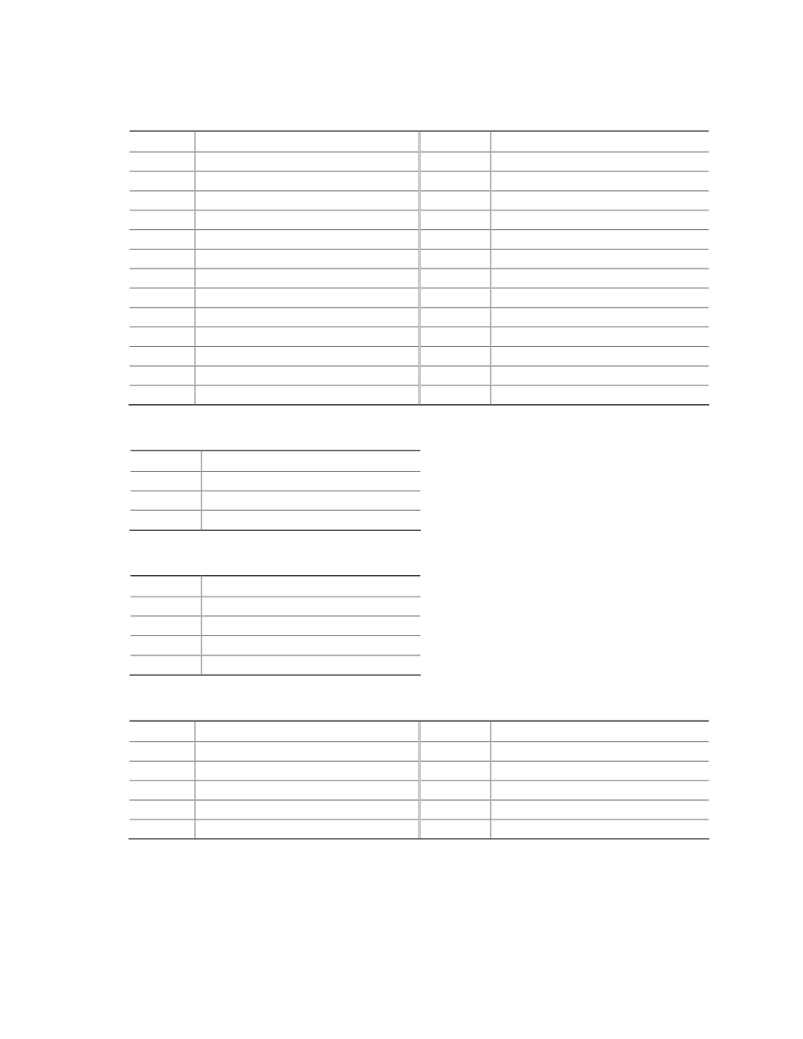
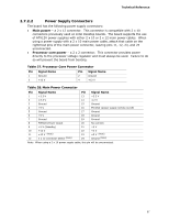
Technical Reference Table 23. Parallel Port Header Pin Signal Name 1 STROBE# 3 PD0 5 PD1 7 PD2 9 PD3 11 PD4 13 PD5 15 PD6 17 PD7 19 ACK# 21 BUSY 23 PERROR 25 SELECT Pin 2 4 6 8 10 12 14 16 18 20 22 24 26 Signal Name AUTOFD# FAULT# INIT# SLCTIN# Ground Ground Ground Ground Ground Ground Ground Ground Key (no pin) Table 24. Front and Rear Chassis Fan Headers Pin Signal Name 1 Control 2 +12 V 3 Tach Table 25. Processor Fan Header Pin Signal Name 1 Ground 2 +12 V 3 FAN_TACH 4 FAN_CONTROL Table 26. Front Panel Audio Header Pin Signal Name Pin 1 [Port 1] Left channel 2 3 [Port 1] Right channel 4 5 [Port 2] Right channel 6 7 SENSE_SEND (Jack detection) 8 9 [Port 2] Left channel 10 Signal Name Ground PRESENCE# (Dongle present) [Port 1] SENSE_RETURN Key (no pin) [Port 2] SENSE_RETURN 55
-
 1
1 -
2
-
3
-
4
-
5
-
6
-
7
-
8
-
9
-
10
-
11
-
12
-
13
-
14
-
15
-
16
-
17
-
18
-
19
-
20
-
21
-
22
-
23
-
24
-
25
-
26
-
27
-
28
-
29
-
30
-
31
-
32
-
33
-
34
-
35
-
36
-
37
-
38
-
39
-
40
-
41
-
42
-
43
-
44
-
45
-
46
-
47
-
48
-
49
-
 50
50 -
 51
51 -
 52
52 -
 53
53 -
 54
54 -
 55
55 -
 56
56 -
 57
57 -
 58
58 -
 59
59 -
 60
60 -
61
-
62
-
63
-
64
-
65
-
66
-
67
-
68
-
69
-
70
-
71
-
72
-
73
-
74
-
75
-
76
-
77
-
78
-
79
-
80
-
81
-
82
-
83
-
84
-
85
-
86
-
87
-
88
-
89
-
90
-
91
-
92
-
93
-
94
-
95
-
96
-
97
-
98
 |
 |