Intel DP43BF Intel Desktop Board DP43BFL Technical Product Specification - Page 21
Intel, P43 Express Chipset - memory compatibility
 |
View all Intel DP43BF manuals
Add to My Manuals
Save this manual to your list of manuals |
Page 21 highlights
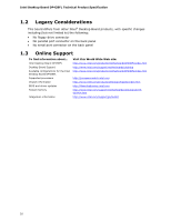
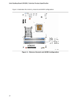
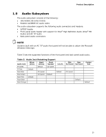
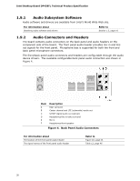
Product Description 1.6 Intel® P43 Express Chipset The Intel P43 Express chipset consists of the following devices: • Intel 82P43 Memory Controller Hub (MCH) with Direct Media Interface (DMI) interconnect • Intel 82801JIB I/O Controller Hub (ICH10) The MCH component provides interfaces to the CPU, memory, PCI Express, and the DMI interconnect. The ICH10 is a centralized controller for the board's I/O paths. The chipset supports the following features: • USB • Serial ATA • Parallel ATA For information about The Intel P43 Express chipset Resources used by the chipset Refer to http://www.intel.com/products/desktop/chipsets/index.htm Chapter 2 1.6.1.1 PCI Express x16 Graphics The MCH also supports an add-in discrete graphics card through the PCI Express 2.0 graphics connector. • PCI Express 2.0 x16: ⎯ Supports PCI Express GEN1 frequency of 1.25 GHz resulting in 2.5 Gb/s each direction (500 MB/s total). Maximum theoretical bandwidth on interface of 4 GB/s in each direction simultaneously, for an aggregate of 8 GB/s when operating in x16 mode. ⎯ Supports PCI Express GEN2 frequency of 2.5 GHz resulting in 5.0 Gb/s each direction (1000 MB/s total). Maximum theoretical bandwidth on interface of 8 GB/s in each direction simultaneously, for an aggregate of 16 GB/s when operating in x16 mode. For information about PCI Express technology Refer to http://www.pcisig.com 1.6.2 USB The board supports up to twelve USB 2.0 ports, supports UHCI and EHCI, and uses UHCI- and EHCI-compatible drivers. The Intel ICH10 provides the USB controller for all ports. The port arrangement is as follows: • Six ports are implemented with stacked back panel connectors • Six ports are routed to three separate front panel USB headers For information about The location of the USB connectors on the back panel The location of the front panel USB headers Refer to Figure 9, page 43 Figure 10, page 44 21
-
 1
1 -
2
-
3
-
4
-
5
-
6
-
7
-
8
-
9
-
10
-
11
-
12
-
13
-
14
-
15
-
 16
16 -
 17
17 -
 18
18 -
 19
19 -
 20
20 -
 21
21 -
 22
22 -
 23
23 -
 24
24 -
 25
25 -
 26
26 -
27
-
28
-
29
-
30
-
31
-
32
-
33
-
34
-
35
-
36
-
37
-
38
-
39
-
40
-
41
-
42
-
43
-
44
-
45
-
46
-
47
-
48
-
49
-
50
-
51
-
52
-
53
-
54
-
55
-
56
-
57
-
58
-
59
-
60
-
61
-
62
-
63
-
64
-
65
-
66
-
67
-
68
-
69
-
70
-
71
-
72
-
73
-
74
-
75
-
76
-
77
-
78
-
79
-
80
-
81
-
82
-
83
-
84
-
85
-
86
-
87
-
88
-
89
-
90
 |
 |