Intel DP55WB Product Specification
Intel DP55WB - Media Series P55 micro-ATX Core i7 i5 LGA1156 Desktop Motherboard Manual
 |
UPC - 735858209151
View all Intel DP55WB manuals
Add to My Manuals
Save this manual to your list of manuals |
Intel DP55WB manual content summary:
- Intel DP55WB | Product Specification - Page 1
September 2009 Order Number: E70716-001US The Intel® Desktop Board DP55WB may contain design defects or errors known as errata that may cause the product to deviate from published specifications. Current characterized errata are documented in the Intel Desktop Board DP55WB Specification Update. - Intel DP55WB | Product Specification - Page 2
® Desktop Board DP55WB Technical Product Specification Date September 2009 This product specification applies to only the standard Intel® Desktop Board DP55WB with BIOS identifier WBIBX10J.86A. Changes to this specification will be published in the Intel Desktop Board DP55WB Specification Update - Intel DP55WB | Product Specification - Page 3
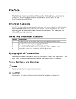
Desktop Board The features supported by the BIOS Setup program A description of the BIOS error messages, beep codes, and POST codes Regulatory compliance and battery disposal information Typographical Conventions This section contains information about the conventions used in this specification - Intel DP55WB | Product Specification - Page 4
Intel Desktop Board DP55WB Technical Product Specification Other Common Notation # GB GB/s Gb/s KB Kbit kbits/s MB MB/s Mbit Mbits/s xxh x.x V * Used after a signal name to identify an active-low signal (such - Intel DP55WB | Product Specification - Page 5
13 1.3 Online Support 14 1.4 Processor 14 1.5 System Memory 15 1.5.1 Memory Configurations 16 1.6 Intel® P55 Express Chipset 18 1.6.1 USB 18 1.6.2 SATA Interfaces 19 1.7 Real-Time Clock Subsystem 20 1.8 Audio Subsystem 20 1.8.1 Audio Subsystem Software 21 1.8.2 Audio Connectors and Headers - Intel DP55WB | Product Specification - Page 6
Intel Desktop Board DP55WB Technical Product Specification 2.5 Electrical Considerations 52 2.5.1 Power Supply Considerations 52 2.5.2 Fan Header Current Capability 53 2.5.3 Add-in Board Considerations 53 2.6 Thermal Considerations 53 2.7 Reliability 56 2.8 Environmental 56 3 Overview of BIOS - Intel DP55WB | Product Specification - Page 7
Connectors and Headers 39 11 Connection Diagram for Front Panel Header 45 12 Connection Diagram for Front Panel USB Headers 47 13 Connection Diagram for Front Panel USB Header (with Intel Z-U130 USB Solid-State Drive, or Compatible Device, Support 47 14 Connection Diagram for IEEE 1394a Header - Intel DP55WB | Product Specification - Page 8
Intel Desktop Board DP55WB Technical Product Specification 26. Thermal Considerations for Components 55 27. Environmental Specifications 56 28. BIOS Setup Program Menu Bar 58 29. BIOS Setup Program Function Keys 58 30. Acceptable Drives/Media Types for BIOS Recovery 61 31. Boot Device Menu - Intel DP55WB | Product Specification - Page 9
(9.60 inches by 9.60 inches [243.84 millimeters by 243.84 millimeters]) Processor Memory Chipset Audio Peripheral Interfaces BIOS Instantly Available PC Technology LAN Support • Intel® Core™ i7 and Core i5 processors in an LGA1156 socket ― One PCI Express* 2.0 x16 Graphics interface ― Integrated - Intel DP55WB | Product Specification - Page 10
Intel Desktop Board DP55WB Technical Product Specification Table 1. Feature Summary (continued) Expansion Capabilities using voltage control (4-pin fan headers front, rear, and processor) with selectable support in BIOS for 3 wire fans • Support for Platform Environmental Control Interface (PECI - Intel DP55WB | Product Specification - Page 11
Product Description 1.1.2 Board Layout Figure 1 shows the location of the major components on Intel Desktop Board DP55WB. Figure 1. Major Board Components 11 - Intel DP55WB | Product Specification - Page 12
Desktop Board DP55WB Technical Product Specification Table 2 lists the components identified in Figure 1. Table 2. Components Shown in Figure 1 Item/callout from Figure 1 A B C D E F G H I J K L M N O P Q R S T U V W X Y Z Description PCI Conventional bus add-in card connector Front panel audio - Intel DP55WB | Product Specification - Page 13
Block Diagram Figure 2 is a block diagram of the major functional areas of the board. Figure 2. Block Diagram 1.2 Legacy Considerations This board differs from other Intel Desktop Board products, with specific changes including (but not limited to) the following: • No parallel port connector • No - Intel DP55WB | Product Specification - Page 14
Intel Desktop Board DP55WB Technical Product Specification 1.3 Online Support To find information about... Intel Desktop Board DP55WB Desktop Board Support Available configurations for the Intel Desktop Board DP55WB Supported processors Chipset information BIOS and driver updates Tested memory - Intel DP55WB | Product Specification - Page 15
with all applicable DDR SDRAM memory specifications, the board should be populated with DIMMs that support the Serial Presence Detect (SPD) data structure. This allows the BIOS to read the SPD data and program the chipset to accurately configure memory settings for optimum performance. If non - Intel DP55WB | Product Specification - Page 16
Intel Desktop Board DP55WB Technical Product Specification 1.5.1 Memory Configurations The Intel Core i7 and Core i5 processors in the LGA1156 socket support the following types of memory organization: • Dual channel (Interleaved) mode. This mode offers the highest throughput for real world - Intel DP55WB | Product Specification - Page 17
channel and DIMM configuration. Figure 3. Memory Channel and DIMM Configuration NOTE The Intel P55 Express Chipset requires memory to be populated in the Channel A, DIMM 0 socket. For best memory performance always install memory into the blue DIMM memory sockets if only installing two DIMMs in - Intel DP55WB | Product Specification - Page 18
Intel Desktop Board DP55WB Technical Product Specification 1.6 Intel® P55 Express Chipset Intel P55 Express Chipset with Direct Media Interface (DMI) interconnect provides interfaces to the processor and the USB, SATA, LPC, LAN, PCI, PCIe interfaces. The Intel P55 Express Chipset is a centralized - Intel DP55WB | Product Specification - Page 19
the Intel P55 Express Chipset: • RAID 0 - data striping • RAID 1 - data mirroring • RAID 0+1 (or RAID 10) - data striping and mirroring • RAID 5 - distributed parity NOTE In order to use supported RAID features, you must first enable RAID in the BIOS. Also, during Microsoft Windows XP installation - Intel DP55WB | Product Specification - Page 20
Intel Desktop Board DP55WB Technical Product Specification 1.7 Real-Time Clock Subsystem A coin-cell battery (CR2032) powers the real-time clock and CMOS memory. When the computer is not plugged into a wall socket, the battery has an estimated life of three years. When the computer is plugged in, - Intel DP55WB | Product Specification - Page 21
mic in and line out signals for front panel audio connectors) • S/PDIF audio header (1 x 4-pin header) 1.8.3 6-Channel (5.1) Audio Subsystem The 6-channel (5.1) audio subsystem includes the following: • Intel P55 Express Chipset • Realtek ALC888-VC2-GR audio codec • A signal-to-noise (S/N) ratio of - Intel DP55WB | Product Specification - Page 22
Desktop Board DP55WB Technical Product Specification NOTE The back panel audio line out connector is designed to power headphones or amplified speakers only. Poor audio quality occurs if passive (non-amplified) speakers are connected to this output. For information about The locations of the front - Intel DP55WB | Product Specification - Page 23
1.9.2 LAN Subsystem Software LAN software and drivers are available from Intel's World Wide Web site. For information about Obtaining LAN software and drivers Refer to http://downloadcenter.intel.com 1.9.3 RJ-45 LAN Connector with Integrated LEDs Two LEDs are built into the RJ-45 LAN connector - Intel DP55WB | Product Specification - Page 24
Intel Desktop Board DP55WB Technical Product Specification 1.10 Hardware Management Subsystem The hardware management features enable the board to be compatible with the Wired for Management (WfM) specification. The board Thermal sensor in the processor, the Hardware Monitoring The board supports a - Intel DP55WB | Product Specification - Page 25
6 shows the locations of the thermal sensors and fan headers. Item A B C D E F Description Rear chassis fan header Processor fan header Thermal diode, located on the processor die Hardware Monitoring ASIC Front chassis fan header Remote thermal diode Figure 6. Thermal Sensors and Fan Headers 25 - Intel DP55WB | Product Specification - Page 26
Intel Desktop Board DP55WB Technical Product Specification 1.11 Power Management Power management is implemented at several levels, including: • Software support through Advanced Configuration and Power Interface (ACPI) • Hardware support: ⎯ Power connector ⎯ Fan headers ⎯ LAN wake capabilities ⎯ - Intel DP55WB | Product Specification - Page 27
operating system uses information from applications and user settings to put the system as a whole into a low-power state. Table 7 lists the power states supported by the board along with the associated system power targets. See the ACPI specification for a complete description of the various system - Intel DP55WB | Product Specification - Page 28
Desktop Board DP55WB Technical Product Specification 1.11.1.2 Wake-up Devices and Events Table 8 lists the devices or specific events that can wake the computer from specific states. Table 8. Wake-up Devices and Events These devices/events can wake up the computer... Power switch RTC alarm LAN - Intel DP55WB | Product Specification - Page 29
off). The computer's response can be set using the Last Power State feature in the BIOS Setup program's Boot menu. For information board is off or in the S3, S4, or S5 state • Each fan header is wired to a fan tachometer input of the hardware monitoring and fan control ASIC • All fan headers support - Intel DP55WB | Product Specification - Page 30
Intel Desktop Board DP55WB Technical Product Specification 1.11.2.3 LAN Wake Capabilities CAUTION For LAN wake capabilities, the +5 V standby line for the power supply must be capable of providing adequate +5 V standby current. Failure to provide adequate standby current when implementing LAN wake - Intel DP55WB | Product Specification - Page 31
Conventional bus is asserted, the computer wakes from an ACPI S1, S3, S4, or S5 state (with Wake on PME enabled in the BIOS). 1.11.2.7 WAKE# Signal Wake-up Support When the WAKE# signal on the PCI Express bus is asserted, the computer wakes from an ACPI S1, S3, S4, or S5 - Intel DP55WB | Product Specification - Page 32
Intel Desktop Board DP55WB Technical Product Specification 1.11.2.8 +5 V Standby Power Indicator LED The +5 V standby power installing or removing any devices connected to the board. Failure to do so could damage the board and any attached devices. Figure 7. Location of the Standby Power LED - Intel DP55WB | Product Specification - Page 33
: Version 5.0 Category D requirements. For information about ENERGY STAR requirements and recommended configurations Refer to http://www.intel.com/go/energystar Intel Desktop Board DP55WB also meets the following international program requirements: • Korea E-Standby • European Union ErP 33 - Intel DP55WB | Product Specification - Page 34
Intel Desktop Board DP55WB Technical Product Specification 34 - Intel DP55WB | Product Specification - Page 35
2 Technical Reference 2.1 Memory Resources 2.1.1 Addressable Memory The board utilizes 16 GB of addressable system memory. Typically the address space that is allocated for PCI Conventional bus add-in cards, PCI Express configuration space, BIOS (SPI Flash device), and chipset overhead resides above - Intel DP55WB | Product Specification - Page 36
Intel Desktop Board DP55WB Technical Product Specification Figure 8. Detailed System Memory Address Map 36 - Intel DP55WB | Product Specification - Page 37
on video adapter used. Video memory and BIOS Extended BIOS data (movable by memory manager software) Extended conventional memory Conventional memory 2.2 Connectors and Headers CAUTION Only the following connectors and headers have overcurrent protection: back panel and front panel USB, as well as - Intel DP55WB | Product Specification - Page 38
Intel Desktop Board DP55WB Technical Product Specification 2.2.1 Back Panel Connectors Figure 9 shows the location of the back panel connectors for the board. Item A B C D E F G H Description USB ports IEEE 1394a connector USB ports LAN USB ports Line in Line out Mic in Figure 9. Back Panel - Intel DP55WB | Product Specification - Page 39
Technical Reference 2.2.2 Component-side Connectors and Headers Figure 10 shows the locations of the component-side connectors and headers. Figure 10. Component-side Connectors and Headers 39 - Intel DP55WB | Product Specification - Page 40
DP55WB Technical Product Specification Table 10 lists the component-side connectors and headers identified in Figure 10. Table 10. Component-side Connectors and Headers Shown in Figure 10 Item/callout from Figure 10 Description A PCI Conventional bus add-in card connector B Front panel audio - Intel DP55WB | Product Specification - Page 41
9 Key (no pin) Pin 2 4 6 8 10 Signal Name Data A (negative) Ground Data B (negative) +12 V DC Ground Table 12. Front Panel Audio Header for Intel HD Audio Pin Signal Name Pin Signal Name 1 [Port 1] Left channel 2 Ground 3 [Port 1] Right channel 4 PRESENCE# (Dongle present) 5 [Port - Intel DP55WB | Product Specification - Page 42
Intel Desktop Board DP55WB Technical Product Specification Table 29. Front Panel USB Header (with Intel Z-U130 USB Solid-State Drive, or Compatible Device, Support Intrusion Header Pin Signal Name 1 Intruder# 2 Ground Table 17. Processor, Front, and Rear Chassis (4-Pin) Fan Headers Pin 1 2 3 - Intel DP55WB | Product Specification - Page 43
PCI Conventional bus add-in boards with SMBus support to access sensor data on the desktop board. The specific SMBus signals are as follows: 12 connector. This connector is compatible with 2 x 10 connectors previously used on Intel Desktop boards. The board supports the use of ATX12V power supplies - Intel DP55WB | Product Specification - Page 44
Intel Desktop Board DP55WB Technical Product Specification Table 19. Main Power Connector Pin Signal Name 1 +3.3 V 2 +3.3 V 3 Ground Pin Signal Name 13 +3.3 V 14 -12 V 15 Ground 4 +5 V 5 Ground 6 +5 V 7 Ground 16 PS-ON# (power supply remote - Intel DP55WB | Product Specification - Page 45
signal names of the front panel header. Figure 11 is a connection diagram for the front panel header. Table 20. Front Panel Header Pin Signal In/ Out Description Hard Drive Activity LED 1 HD_PWR Out Hard disk LED pull-up to +5 V 3 HDA# Out Hard disk active LED Reset Switch 5 Ground - Intel DP55WB | Product Specification - Page 46
Intel Desktop Board DP55WB Technical Product Specification 2.2.2.4.2 Reset Switch Header Pins 5 and 7 can be connected to a momentary single pole, single throw (SPST) type switch that is normally open. When the switch is closed, the board resets and runs the POST. 2.2.2.4.3 Power/Sleep LED - Intel DP55WB | Product Specification - Page 47
• Use only a front panel USB connector that conforms to the USB 2.0 specification for high-speed USB devices. Figure 12. Connection Diagram for Front Panel USB Headers Figure 13. Connection Diagram for Front Panel USB Header (with Intel Z-U130 USB Solid-State Drive, or Compatible Device, Support) 47 - Intel DP55WB | Product Specification - Page 48
Intel Desktop Board DP55WB Technical Product Specification 2.2.2.6 Front Panel IEEE 1394a Header Figure 14 is a connection diagram for the IEEE 1394a header. NOTE • The +12 V DC power on the IEEE 1394a header is fused. • - Intel DP55WB | Product Specification - Page 49
program's mode. Table 23 describes the jumper settings for the three modes: normal, configure, and recovery. When the jumper is set to configure mode and the computer is powered-up, the BIOS compares the processor version and the microcode version in the BIOS and reports if the two match. Figure 15 - Intel DP55WB | Product Specification - Page 50
Intel Desktop Board DP55WB Technical Product Specification Table 23. BIOS Setup Configuration Jumper Settings Function/Mode Normal Jumper Setting 1-2 Configuration The BIOS uses current configuration information and passwords for booting. Configure 2-3 Recovery None After the POST runs, - Intel DP55WB | Product Specification - Page 51
form factor for the board. Dimensions are given in inches [millimeters]. The outer dimensions are 9.60 inches by 9.60 inches [243.84 millimeters by 243.84 millimeters]. Location of the I/O connectors and mounting holes are in compliance with the ATX specification. Figure 16. Board Dimensions 51 - Intel DP55WB | Product Specification - Page 52
Intel Desktop Board DP55WB Technical Product Specification 2.5 Electrical Considerations 2.5.1 Power Supply supported 95 W processor (see Section 1.4 on page 14 for a list of supported processors), 1 GB DDR3 RAM, one high end video card, one hard disk drive, one optical drive, and all board - Intel DP55WB | Product Specification - Page 53
processor and/or voltage regulator or, in some instances, damage to the board. For a list of chassis that have been tested with Intel desktop boards please refer to the following website: http://www3.intel . Intel makes no warranties or representations that merely following the instructions presented - Intel DP55WB | Product Specification - Page 54
Intel Desktop Board DP55WB Technical Product Specification CAUTION Ensure that the ambient temperature does not exceed the board's maximum temperature zones. Item A B C Description Processor voltage regulator area Processor Intel P55 Express Chipset Figure 17. Localized High Temperature Zones 54 - Intel DP55WB | Product Specification - Page 55
processor case temperature, see processor datasheets and processor specification updates Intel P55 Express Chipset 107 oC For information about Processor datasheets and specification updates Intel P55 Express Chipset Refer to Section 1.3, page 14 http://www.intel.com/products/desktop/ chipsets - Intel DP55WB | Product Specification - Page 56
Intel Desktop Board DP55WB Technical Product Specification 2.7 Reliability The Mean Time Between Failures (MTBF) prediction is calculated using component and subassembly random failure rates. The calculation is based on the Bellcore Reliability - Intel DP55WB | Product Specification - Page 57
The board uses an Intel BIOS that is stored in the Serial Peripheral Interface Flash Memory (SPI Flash) and can be updated using a disk-based program. The SPI Flash contains the BIOS Setup program, POST, the PCI auto-configuration utility, LAN EEPROM information, and Plug and Play support. The BIOS - Intel DP55WB | Product Specification - Page 58
Intel Desktop Board DP55WB Technical Product Specification Table 28 lists the BIOS Setup program menu features. Table 28. BIOS Setup Program Menu Bar Maintenance Main Advanced Performance Security Clears passwords and displays processor information Displays processor and memory configuration - Intel DP55WB | Product Specification - Page 59
set to Disabled in the BIOS Setup program.) 6. After the operating system loads the USB drivers, all legacy and non-legacy USB devices are recognized by the operating system, and Legacy USB support from the BIOS is no longer used. 7. Additional USB legacy feature options can be access by using Intel - Intel DP55WB | Product Specification - Page 60
Intel Desktop Board DP55WB Technical Product Specification To install an operating system that supports USB, verify that Legacy USB support in the BIOS Setup program is set to Enabled and follow the operating system's installation instructions. 3.6 BIOS Updates The BIOS can be updated using either - Intel DP55WB | Product Specification - Page 61
.com/products/motherboard/DP55WB/ tools.htm and http://developer.intel.com/design/motherbd/software.htm 3.7 BIOS Recovery It is unlikely that anything will interrupt a BIOS update; however, if an interruption occurs, the BIOS could be damaged. Table 30 lists the drives and media types that can and - Intel DP55WB | Product Specification - Page 62
Intel Desktop Board DP55WB Technical Product Specification 3.8 Boot Options In the BIOS Setup program, the user can choose to boot from a diskette drive, hard drive, USB drive, USB flash drive, CD-ROM, or the network. The default setting allows booting from the onboard LAN or a network add-in card - Intel DP55WB | Product Specification - Page 63
monitors. Some monitors initialize and communicate with the BIOS more quickly, which enables the system to boot more quickly. 3.9.2 BIOS Boot Optimizations Use of the following BIOS Setup program settings reduces the POST execution time. • In the Boot Menu, set the hard disk drive as the first boot - Intel DP55WB | Product Specification - Page 64
Intel Desktop Board DP55WB Technical Product Specification 3.10 BIOS Security Features The BIOS includes security features that restrict access to the BIOS Setup program and who can boot the computer. A supervisor password and a user password can be set for the BIOS Setup program and for booting - Intel DP55WB | Product Specification - Page 65
enhancements when using Intel Core i7 and Intel Core i5 processors in an LGA1156 socket. • Host Clock frequency adjustment • Processor multiplier adjustment (processor multiplier can only be adjusted down) • Processor voltage adjustment • Memory multiplier adjustment • Memory voltage adjustment - Intel DP55WB | Product Specification - Page 66
Intel Desktop Board DP55WB Technical Product Specification 66 - Intel DP55WB | Product Specification - Page 67
occurs during POST, the BIOS causes the board's speaker to beep an error message describing the problem (see Table 33). Table 33. BIOS Beep Codes Type Pattern F2 Setup/F10 Boot Menu One 0.5 second beep when BIOS is ready to Prompt accept keyboard input BIOS update in progress None Video - Intel DP55WB | Product Specification - Page 68
Intel Desktop Board DP55WB Technical Product Specification 4.3 Front-panel Power LED Blink Codes Whenever a recoverable error occurs during POST, the BIOS causes the board's front panel power LED to blink an error message describing the problem (see Table 34). Table 34. Front-panel Power LED - Intel DP55WB | Product Specification - Page 69
Category/Subsystem 00 - 0F Debug codes: Can be used by any PEIM/driver for debug. 10 - 1F Host Processors: 1F is an unrecoverable CPU error. 20 - 2F Memory/Chipset: 2F is no memory detected or no useful memory detected. 30 - 3F Recovery: 3F indicated recovery failure. 40 - 4F Reserved for - Intel DP55WB | Product Specification - Page 70
Intel Desktop Board DP55WB Technical Product Specification Table 37. Port 80h POST Codes POST Code Description of POST Operation Host Processor 10 Power-on initialization of the host processor (Boot Strap Processor) 11 Host processor cache initialization (including APs) 12 Starting - Intel DP55WB | Product Specification - Page 71
Messages and Beep Codes Table 37. Port 80h POST Codes (continued) POST Code Description of POST Operation Keyboard (USB) 90 Resetting keyboard 91 Disabling keyboard 92 Detecting presence of keyboard 93 Enabling the keyboard 94 Clearing keyboard input buffer 95 Instructing keyboard - Intel DP55WB | Product Specification - Page 72
Intel Desktop Board DP55WB Technical Product Specification Table 37. Port 80h POST Codes (continued) POST Code Description of POST Operation DXE Drivers E7 Waiting for user input E8 Checking password E9 Entering BIOS setup EB Calling Legacy Option ROMs Runtime Phase/EFI OS Boot F4 - Intel DP55WB | Product Specification - Page 73
Error Messages and Beep Codes Table 38. Typical Port 80h POST Sequence POST Code Description 21 Initializing a chipset component 22 Reading SPD from memory DIMMs 23 Detecting presence of memory DIMMs 25 Configuring memory 28 Testing memory 34 Loading recovery capsule E4 Entered DXE - Intel DP55WB | Product Specification - Page 74
Intel Desktop Board DP55WB Technical Product Specification 74 - Intel DP55WB | Product Specification - Page 75
Safety standards • European Union Declaration of Conformity statement • Product Ecology statements • Electromagnetic Compatibility (EMC) standards • Product certification markings 5.1.1 Safety Standards Intel Desktop Board DP55WB complies with the safety standards stated in Table 39 when correctly - Intel DP55WB | Product Specification - Page 76
Intel Desktop Board DP55WB Technical Product Specification 5.1.2 European Union Declaration of Conformity Statement We, Intel Corporation, declare under our sole responsibility that the product Intel® Desktop Board DP55WB is in conformity with all applicable essential requirements necessary for CE - Intel DP55WB | Product Specification - Page 77
of this program, including the scope of covered products, available locations, shipping instructions, terms and conditions, etc Intel Product Recycling Program http://www.intel.com/intel/other/ehs/product_ecology Deutsch Als Teil von Intels Engagement für den Umweltschutz hat das Unternehmen das - Intel DP55WB | Product Specification - Page 78
Intel Desktop Board DP55WB Technical Product Specification Español Como parte de su compromiso de responsabilidad medioambiental, Intel ha implantado el programa de reciclaje de productos Intel, que permite que los consumidores al detalle de los productos Intel devuelvan los productos usados en los - Intel DP55WB | Product Specification - Page 79
kayıtlar ve şartlar v.s dahil bütün ayrıntılarını ögrenmek için lütfen http://www.intel.com/intel/other/ehs/product_ecology Web sayfasına gidin. 5.1.3.3 Lead Free Desktop Board This Intel Desktop Board is a European Union Restriction of Hazardous Substances (EU RoHS Directive 2002/95/EC) compliant - Intel DP55WB | Product Specification - Page 80
Intel Desktop Board DP55WB Technical Product Specification Table 40. Lead-Free Board Markings Description Lead-Free 2nd Level Interconnect: This symbol is used to identify electrical and electronic assemblies and components in which the lead (Pb) concentration level in the desktop board substrate - Intel DP55WB | Product Specification - Page 81
Intel Desktop Board DP55WB complies with the EMC regulations stated in Table 41 when correctly installed in a compatible 2007.04 KN-22, KN-24 CNS 13438:2006 Title 47 of the Code of Federal Regulations, Part15, Subpart B, Radio Frequency Devices. (USA) Interference- to the instruction manual. 81 - Intel DP55WB | Product Specification - Page 82
Intel Desktop Board DP55WB Technical Product Specification Korean Class B statement Intel supplier code number, N-232. Japan VCCI (Voluntary Control Council for Interference) mark. S. Korea KCC (Korean Communications Commission) mark. Includes adjacent KCC certification number: CPU-DP55WB - Intel DP55WB | Product Specification - Page 83
Regulatory Compliance and Battery Disposal Information 5.2 Battery Disposal Information CAUTION Risk of explosion if the battery is replaced with an incorrect type. Batteries should be recycled where possible. Disposal of used batteries must be in accordance with local environmental regulations. - Intel DP55WB | Product Specification - Page 84
Intel Desktop Board DP55WB Technical Product Specification PRECAUCIÓN Existe peligro de explosión si la pila no se cambia de forma adecuada. Utilice solamente pilas iguales o del mismo tipo que las recomendadas por - Intel DP55WB | Product Specification - Page 85
Regulatory Compliance and Battery Disposal Information AWAS Risiko letupan wujud jika bateri digantikan dengan jenis yang tidak betul. Bateri sepatutnya dikitar semula jika boleh. Pelupusan bateri terpakai mestilah mematuhi peraturan alam sekitar tempatan. OSTRZEŻENIE Istnieje niebezpieczeństwo - Intel DP55WB | Product Specification - Page 86
Intel Desktop Board DP55WB Technical Product Specification 86
-
 1
1 -
 2
2 -
 3
3 -
 4
4 -
 5
5 -
 6
6 -
 7
7 -
8
-
9
-
10
-
11
-
12
-
13
-
14
-
15
-
16
-
17
-
18
-
19
-
20
-
21
-
22
-
23
-
24
-
25
-
26
-
27
-
28
-
29
-
30
-
31
-
32
-
33
-
34
-
35
-
36
-
37
-
38
-
39
-
40
-
41
-
42
-
43
-
44
-
45
-
46
-
47
-
48
-
49
-
50
-
51
-
52
-
53
-
54
-
55
-
56
-
57
-
58
-
59
-
60
-
61
-
62
-
63
-
64
-
65
-
66
-
67
-
68
-
69
-
70
-
71
-
72
-
73
-
74
-
75
-
76
-
77
-
78
-
79
-
80
-
81
-
82
-
83
-
84
-
85
-
86
 |
 |

Intel® Desktop Board
DP55WB
Technical Product Specification
September 2009
Order Number:
E70716-001US
The Intel
®
Desktop Board DP55WB may contain design defects or errors known as errata that may cause the product to deviate from published
specifications.
Current characterized errata are documented in the Intel Desktop Board DP55WB Specification Update.