Intel DP55WB Product Specification - Page 25
Thermal Monitoring
 |
UPC - 735858209151
View all Intel DP55WB manuals
Add to My Manuals
Save this manual to your list of manuals |
Page 25 highlights
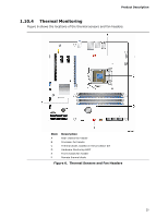
Product Description 1.10.4 Thermal Monitoring Figure 6 shows the locations of the thermal sensors and fan headers. Item A B C D E F Description Rear chassis fan header Processor fan header Thermal diode, located on the processor die Hardware Monitoring ASIC Front chassis fan header Remote thermal diode Figure 6. Thermal Sensors and Fan Headers 25
-
 1
1 -
2
-
3
-
4
-
5
-
6
-
7
-
8
-
9
-
10
-
11
-
12
-
13
-
14
-
15
-
16
-
17
-
18
-
19
-
 20
20 -
 21
21 -
 22
22 -
 23
23 -
 24
24 -
 25
25 -
 26
26 -
 27
27 -
 28
28 -
 29
29 -
 30
30 -
31
-
32
-
33
-
34
-
35
-
36
-
37
-
38
-
39
-
40
-
41
-
42
-
43
-
44
-
45
-
46
-
47
-
48
-
49
-
50
-
51
-
52
-
53
-
54
-
55
-
56
-
57
-
58
-
59
-
60
-
61
-
62
-
63
-
64
-
65
-
66
-
67
-
68
-
69
-
70
-
71
-
72
-
73
-
74
-
75
-
76
-
77
-
78
-
79
-
80
-
81
-
82
-
83
-
84
-
85
-
86
 |
 |

Product Description
25
1.10.4
Thermal Monitoring
Figure 6 shows the locations of the thermal sensors and fan headers.
Item
Description
A
Rear chassis fan header
B
Processor fan header
C
Thermal diode, located on the processor die
D
Hardware Monitoring ASIC
E
Front chassis fan header
F
Remote thermal diode
Figure 6.
Thermal Sensors and Fan Headers