Intel DP55WB Product Specification - Page 29
Power Connector, 11.2.2, Fan Headers - bios
 |
UPC - 735858209151
View all Intel DP55WB manuals
Add to My Manuals
Save this manual to your list of manuals |
Page 29 highlights
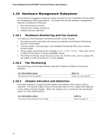
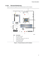
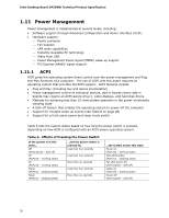
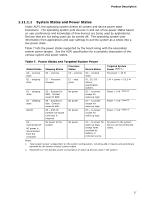
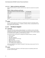
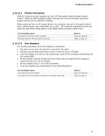
Product Description 1.11.2.1 Power Connector ATX12V-compliant power supplies can turn off the system power through system control. When an ACPI-enabled system receives the correct command, the power supply removes all non-standby voltages. When resuming from an AC power failure, the computer returns to the power state it was in before power was interrupted (on or off). The computer's response can be set using the Last Power State feature in the BIOS Setup program's Boot menu. For information about The location of the main power connector The signal names of the main power connector Refer to Figure 10, page 39 Table 19, page 44 1.11.2.2 Fan Headers The function/operation of the fan headers is as follows: • The fans are on when the board is in the S0 or S1 state • The fans are off when the board is off or in the S3, S4, or S5 state • Each fan header is wired to a fan tachometer input of the hardware monitoring and fan control ASIC • All fan headers support closed-loop fan control that can adjust the fan speed or switch the fan on or off as needed • All fan headers have a +12 V DC connection • 4-pin fan headers are controlled by Pulse Width Modulation For information about The location of the fan headers The location of the fan headers and sensors for thermal monitoring Refer to Figure 10, page 39 Figure 6, page 25 29
-
 1
1 -
2
-
3
-
4
-
5
-
6
-
7
-
8
-
9
-
10
-
11
-
12
-
13
-
14
-
15
-
16
-
17
-
18
-
19
-
20
-
21
-
22
-
23
-
 24
24 -
 25
25 -
 26
26 -
 27
27 -
 28
28 -
 29
29 -
 30
30 -
 31
31 -
 32
32 -
 33
33 -
 34
34 -
35
-
36
-
37
-
38
-
39
-
40
-
41
-
42
-
43
-
44
-
45
-
46
-
47
-
48
-
49
-
50
-
51
-
52
-
53
-
54
-
55
-
56
-
57
-
58
-
59
-
60
-
61
-
62
-
63
-
64
-
65
-
66
-
67
-
68
-
69
-
70
-
71
-
72
-
73
-
74
-
75
-
76
-
77
-
78
-
79
-
80
-
81
-
82
-
83
-
84
-
85
-
86
 |
 |
