Intel DP55WB Product Specification - Page 12
Table 2., Components Shown - lga1156
 |
UPC - 735858209151
View all Intel DP55WB manuals
Add to My Manuals
Save this manual to your list of manuals |
Page 12 highlights
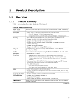
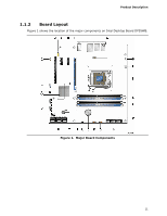
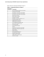
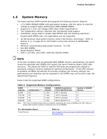
Intel Desktop Board DP55WB Technical Product Specification Table 2 lists the components identified in Figure 1. Table 2. Components Shown in Figure 1 Item/callout from Figure 1 A B C D E F G H I J K L M N O P Q R S T U V W X Y Z Description PCI Conventional bus add-in card connector Front panel audio header PCI Express x1 bus add-in card connector PCI Express x1 bus add-in card connector PCI Express x16 bus add-in card connector Back panel connectors Rear chassis fan header Processor fan header Processor core power connector (2 x 2) LGA1156 processor socket DIMM Channel A sockets (2) DIMM Channel B sockets (2) +5 V Standby Power Indicator LED Main power connector (2 x 12) Front panel header Front chassis fan header Battery Alternate front panel power LED header BIOS Setup configuration jumper block Piezo Speaker SATA connectors Front panel USB headers (3) Intel P55 Express Chipset Chassis intrusion header IEEE 1394a front panel header S/PDIF out header 12
-
 1
1 -
2
-
3
-
4
-
5
-
6
-
 7
7 -
 8
8 -
 9
9 -
 10
10 -
 11
11 -
 12
12 -
 13
13 -
 14
14 -
 15
15 -
 16
16 -
 17
17 -
18
-
19
-
20
-
21
-
22
-
23
-
24
-
25
-
26
-
27
-
28
-
29
-
30
-
31
-
32
-
33
-
34
-
35
-
36
-
37
-
38
-
39
-
40
-
41
-
42
-
43
-
44
-
45
-
46
-
47
-
48
-
49
-
50
-
51
-
52
-
53
-
54
-
55
-
56
-
57
-
58
-
59
-
60
-
61
-
62
-
63
-
64
-
65
-
66
-
67
-
68
-
69
-
70
-
71
-
72
-
73
-
74
-
75
-
76
-
77
-
78
-
79
-
80
-
81
-
82
-
83
-
84
-
85
-
86
 |
 |
