Intel DQ57TM Product Specification - Page 58
Clear CMOS Header
 |
View all Intel DQ57TM manuals
Add to My Manuals
Save this manual to your list of manuals |
Page 58 highlights
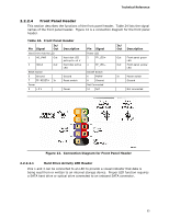
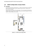
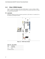
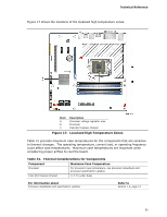
Intel Desktop Board DQ57TM Technical Product Specification 2.4 Clear CMOS Header Figure 15 shows the location of the Clear CMOS header. In order to initiate a CMOS clear, a jumper (not included) must be connected to the jumper block pins for at least two seconds (see Table 28). CAUTION Initiating a CMOS clear when the board is powered on (S0 mode) or in standby (S1 or S3 mode) may damage the board. Figure 15. CMOS Clear Header Table 28. Clear CMOS Pin Function 1-2 Clear CMOS 2-3 N/A No Jumper Normal 58
-
 1
1 -
2
-
3
-
4
-
5
-
6
-
7
-
8
-
9
-
10
-
11
-
12
-
13
-
14
-
15
-
16
-
17
-
18
-
19
-
20
-
21
-
22
-
23
-
24
-
25
-
26
-
27
-
28
-
29
-
30
-
31
-
32
-
33
-
34
-
35
-
36
-
37
-
38
-
39
-
40
-
41
-
42
-
43
-
44
-
45
-
46
-
47
-
48
-
49
-
50
-
51
-
52
-
 53
53 -
 54
54 -
 55
55 -
 56
56 -
 57
57 -
 58
58 -
 59
59 -
 60
60 -
 61
61 -
 62
62 -
 63
63 -
64
-
65
-
66
-
67
-
68
-
69
-
70
-
71
-
72
-
73
-
74
-
75
-
76
-
77
-
78
-
79
-
80
-
81
-
82
-
83
-
84
-
85
-
86
-
87
-
88
-
89
-
90
-
91
-
92
-
93
-
94
 |
 |

Intel Desktop Board DQ57TM Technical Product Specification
58
2.4
Clear CMOS Header
Figure 15 shows the location of the
Clear CMOS header. In order to initiate a CMOS
clear, a jumper (not included) must be connected to the jumper block pins for at least
two seconds (see Table 28).
CAUTION
Initiating a CMOS clear when the board is powered on (S0 mode) or in standby (S1 or
S3 mode) may damage the board.
Figure 15.
CMOS Clear Header
Table 28.
Clear CMOS
Pin
Function
1-2
Clear CMOS
2-3
N/A
No Jumper
Normal