Intel DQ57TM Product Specification - Page 7

s, Tables - memory

Page 7 highlights

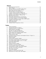
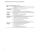
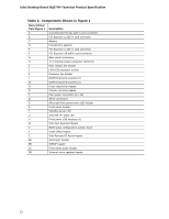
Contents Figures 1. Major Board Components 11 2. Block Diagram 13 3. Memory Channel and DIMM Configuration 17 4. Back Panel Audio Connector Options 22 5. LAN Connector LED Locations 24 6. Thermal Sensors and Fan Headers 26 7. Location of the Intel ME "M" State LED 31 8. Location of the Standby Power LED (Green 40 9. Detailed System Memory Address Map 44 10. Back Panel Connectors 46 11. Component-side Connectors and Headers 47 12. Connection Diagram for Front Panel Header 53 13. Connection Diagram for Front Panel USB Headers 55 14. Location of the Jumper Block 56 15. CMOS Clear Header 58 16. Board Dimensions 59 17. Localized High Temperature Zones 63 Tables 1. Feature Summary 9 2. Components Shown in Figure 1 12 3. Supported Memory Configurations 15 4. LAN Connector LED States 24 5. Intel ME "M" State LED Behavior 30 6. Effects of Pressing the Power Switch 34 7. Power States and Targeted System Power 35 8. Wake-up Devices and Events 36 9. System Memory Map 45 10. Component-side Connectors and Headers Shown in Figure 11 48 11. Serial Port Header 49 12. S/PDIF Header 49 13. Internal Mono Speaker Header 49 14. Front Panel Audio Header for Intel HD Audio 49 15. Front Panel Audio Header for AC '97 Audio 50 16. Front Panel USB Header 50 17. SATA Connectors 50 18. Chassis Intrusion Header 50 19. Processor (4-Pin) Fan Header 51 20. Front and Rear Chassis Fan Headers 51 21. Intel Remote PC Assist Technology Header 51 22. Processor Core Power Connector 52 23. Main Power Connector 52 24. Front Panel Header 53 25. States for a One-Color Power LED 54 26. Alternate Front Panel Power LED Header 54 vii

  • 1
  • 2
  • 3
  • 4
  • 5
  • 6
  • 7
  • 8
  • 9
  • 10
  • 11
  • 12
  • 13
  • 14
  • 15
  • 16
  • 17
  • 18
  • 19
  • 20
  • 21
  • 22
  • 23
  • 24
  • 25
  • 26
  • 27
  • 28
  • 29
  • 30
  • 31
  • 32
  • 33
  • 34
  • 35
  • 36
  • 37
  • 38
  • 39
  • 40
  • 41
  • 42
  • 43
  • 44
  • 45
  • 46
  • 47
  • 48
  • 49
  • 50
  • 51
  • 52
  • 53
  • 54
  • 55
  • 56
  • 57
  • 58
  • 59
  • 60
  • 61
  • 62
  • 63
  • 64
  • 65
  • 66
  • 67
  • 68
  • 69
  • 70
  • 71
  • 72
  • 73
  • 74
  • 75
  • 76
  • 77
  • 78
  • 79
  • 80
  • 81
  • 82
  • 83
  • 84
  • 85
  • 86
  • 87
  • 88
  • 89
  • 90
  • 91
  • 92
  • 93
  • 94

Contents
vii
Figures
1.
Major Board Components
..................................................................
11
2.
Block Diagram
................................................................................
13
3.
Memory Channel and DIMM Configuration
...........................................
17
4.
Back Panel Audio Connector Options
..................................................
22
5.
LAN Connector LED Locations
............................................................
24
6.
Thermal Sensors and Fan Headers
.....................................................
26
7.
Location of the Intel ME “M” State LED
...............................................
31
8.
Location of the Standby Power LED (Green)
........................................
40
9.
Detailed System Memory Address Map
...............................................
44
10. Back Panel Connectors
.....................................................................
46
11. Component-side Connectors and Headers
...........................................
47
12. Connection Diagram for Front Panel Header
........................................
53
13. Connection Diagram for Front Panel USB Headers
................................
55
14. Location of the Jumper Block
.............................................................
56
15. CMOS Clear Header
.........................................................................
58
16. Board Dimensions
...........................................................................
59
17. Localized High Temperature Zones
.....................................................
63
Tables
1.
Feature Summary
..............................................................................
9
2.
Components Shown in Figure 1
.........................................................
12
3.
Supported Memory Configurations
.....................................................
15
4.
LAN Connector LED States
................................................................
24
5.
Intel ME “M” State LED Behavior
........................................................
30
6.
Effects of Pressing the Power Switch
..................................................
34
7.
Power States and Targeted System Power
...........................................
35
8.
Wake-up Devices and Events
............................................................
36
9.
System Memory Map
.......................................................................
45
10. Component-side Connectors and Headers Shown in Figure 11
................
48
11. Serial Port Header
...........................................................................
49
12. S/PDIF Header
................................................................................
49
13. Internal Mono Speaker Header
..........................................................
49
14. Front Panel Audio Header for Intel HD Audio
........................................
49
15. Front Panel Audio Header for AC ’97 Audio
..........................................
50
16. Front Panel USB Header
...................................................................
50
17. SATA Connectors
.............................................................................
50
18. Chassis Intrusion Header
..................................................................
50
19. Processor (4-Pin) Fan Header
............................................................
51
20. Front and Rear Chassis Fan Headers
..................................................
51
21. Intel Remote PC Assist Technology Header
..........................................
51
22. Processor Core Power Connector
........................................................
52
23. Main Power Connector
......................................................................
52
24. Front Panel Header
..........................................................................
53
25. States for a One-Color Power LED
......................................................
54
26. Alternate Front Panel Power LED Header
.............................................
54