Intel E6300 Data Sheet - Page 76
Table 26., Processor Thermal Specifications - processor power consumption
 |
UPC - 735858184649
View all Intel E6300 manuals
Add to My Manuals
Save this manual to your list of manuals |
Page 76 highlights
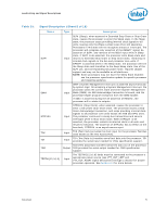
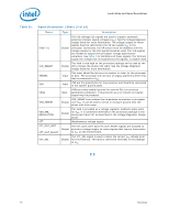
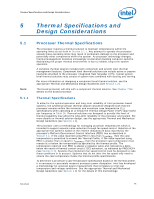
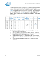
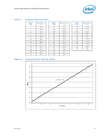
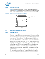
Thermal Specifications and Design Considerations The case temperature is defined at the geometric top center of the processor. Analysis indicates that real applications are unlikely to cause the processor to consume maximum power dissipation for sustained time periods. Intel recommends that complete thermal solution designs target the Thermal Design Power (TDP) indicated in Table 26 instead of the maximum processor power consumption. The Thermal Monitor feature is designed to protect the processor in the unlikely event that an application exceeds the TDP recommendation for a sustained periods of time. For more details on the usage of this feature, see Section 5.2. In all cases the Thermal Monitor or Thermal Monitor 2 feature must be enabled for the processor to remain within specification. Table 26. Processor Thermal Specifications Processor Number Core Frequency (GHz) Thermal Design Power (W)3,4 Extended HALT Power (W)1 Deeper Sleep Power (W)2 775_VR_ CONFIG_06 Guidance5 Minimum Maximum TC (°C) TC (°C) Notes E5200 2.50 65.0 8 E5300 2.66 65.0 8 E5400 2.70 65.0 8 E5500 2.80 65.0 8 E5700 3.00 65.0 8 E5800 3.20 65.0 8 E6300 2.80 65.0 8 E6500 2.93 65.0 8 E6600 3.06 65.0 8 E6700 3.20 65.0 8 E6800 3.33 65.0 8 6 5 4 5 4 5 4 5 6 775_VR_CONFIG 5 6 _06 5 6 (65 W) 5 6 5 6 5 6 5 6 5 See Table 27 and Figure 14 NOTES: 1. Specification is at 36 °C TC and minimum voltage loadline. Specification is ensured by design characterization and not 100% tested. 2. Specification is at 34 °C TC and minimum voltage loadline. Specification is ensured by design characterization and not 100% tested. 3. Thermal Design Power (TDP) should be used for processor thermal solution design targets. The TDP is not the maximum power that the processor can dissipate. 4. This table shows the maximum TDP for a given frequency range. Individual processors may have a lower TDP. Therefore, the maximum TC will vary depending on the TDP of the individual processor. See Figure 14 and Table 27 for the allowed combinations of power and TC. 5. 775_VR_CONFIG_06 guidelines provide a design target for meeting future thermal requirements. 76 Datasheet
-
 1
1 -
2
-
3
-
4
-
5
-
6
-
7
-
8
-
9
-
10
-
11
-
12
-
13
-
14
-
15
-
16
-
17
-
18
-
19
-
20
-
21
-
22
-
23
-
24
-
25
-
26
-
27
-
28
-
29
-
30
-
31
-
32
-
33
-
34
-
35
-
36
-
37
-
38
-
39
-
40
-
41
-
42
-
43
-
44
-
45
-
46
-
47
-
48
-
49
-
50
-
51
-
52
-
53
-
54
-
55
-
56
-
57
-
58
-
59
-
60
-
61
-
62
-
63
-
64
-
65
-
66
-
67
-
68
-
69
-
70
-
 71
71 -
 72
72 -
 73
73 -
 74
74 -
 75
75 -
 76
76 -
 77
77 -
 78
78 -
 79
79 -
 80
80 -
 81
81 -
82
-
83
-
84
-
85
-
86
-
87
-
88
-
89
-
90
-
91
-
92
-
93
-
94
-
95
-
96
-
97
-
98
-
99
-
100
 |
 |