Intel SE7501CW2 Product Guide - Page 63
Replacing a Processor, Raise the socket lever on the processor socket.
 |
UPC - 735858160308
View all Intel SE7501CW2 manuals
Add to My Manuals
Save this manual to your list of manuals |
Page 63 highlights
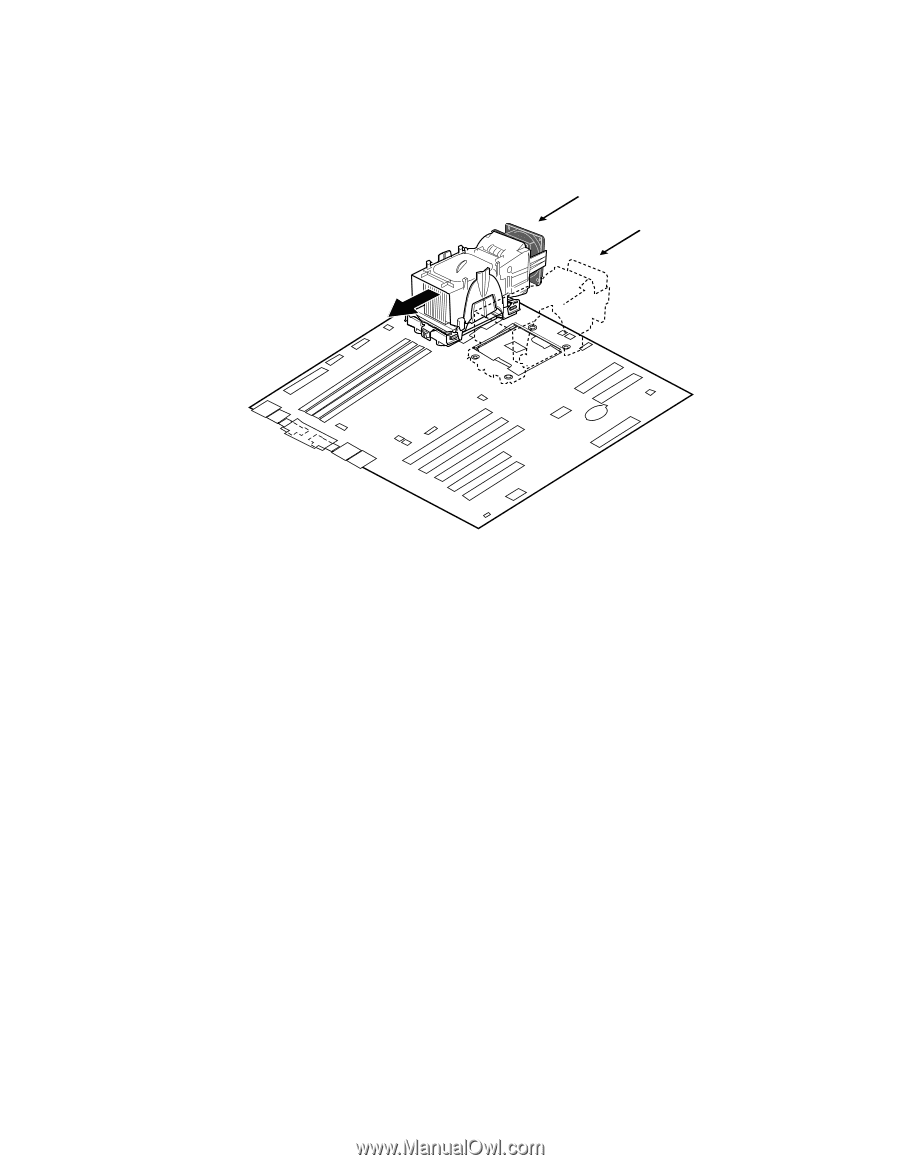
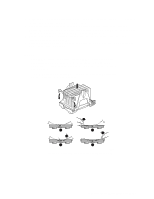
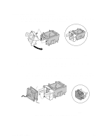
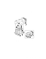
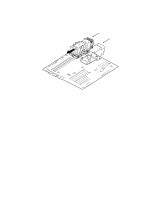
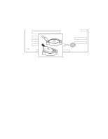
When assembled, the Processor Wind Tunnel will look similar to the figure below. The dashed lines over CPU2 indicate that this processor assembly is only required when configuring the server with two processors. The direction of the airflow is indicated by the arrow at Figure 19, A. CPU1 CPU2 A TP00095 Figure 19. Processor and Wind Tunnel Installed Replacing a Processor 1. Observe the safety and ESD precautions at the beginning of this chapter and the additional cautions given here. 2. Unplug the processor fan cable from the server board. 3. Detach the fan assembly from the PWT retention mechanism by unlatching the clips at the bottom of the fan assembly and then lifting up on the fan assembly. 4. Remove the metal retention mechanism clips from the bottom of the retention mechanism. Unhook each side of each clip and disengage the center latch. 5. Remove the heat sink by slightly spreading the sides of the retention mechanism and lifting straight up on the heat sink. 6. Raise the socket lever on the processor socket. 7. Remove the processor from the socket. 8. Align the pins of the replacement processor with the socket, and insert the processor into the socket. Lower the socket lever completely. ✏ NOTE Make sure the alignment triangle mark and the alignment triangle cutout align correctly. Server Board Installation 63
-
 1
1 -
2
-
3
-
4
-
5
-
6
-
7
-
8
-
9
-
10
-
11
-
12
-
13
-
14
-
15
-
16
-
17
-
18
-
19
-
20
-
21
-
22
-
23
-
24
-
25
-
26
-
27
-
28
-
29
-
30
-
31
-
32
-
33
-
34
-
35
-
36
-
37
-
38
-
39
-
40
-
41
-
42
-
43
-
44
-
45
-
46
-
47
-
48
-
49
-
50
-
51
-
52
-
53
-
54
-
55
-
56
-
57
-
 58
58 -
 59
59 -
 60
60 -
 61
61 -
 62
62 -
 63
63 -
 64
64 -
 65
65 -
 66
66 -
 67
67 -
 68
68 -
69
-
70
-
71
-
72
-
73
-
74
-
75
-
76
-
77
-
78
-
79
-
80
-
81
-
82
-
83
-
84
-
85
-
86
-
87
-
88
-
89
-
90
-
91
-
92
-
93
 |
 |