Intel SSR212CC User Guide
Intel SSR212CC Manual
 |
View all Intel SSR212CC manuals
Add to My Manuals
Save this manual to your list of manuals |
Intel SSR212CC manual content summary:
- Intel SSR212CC | User Guide - Page 1
Intel® Storage System SSR212CC User Guide A Guide for Technically Qualified Assemblers of Intel® Identified Subassemblies/ Products Intel Order Number D55418-002 - Intel SSR212CC | User Guide - Page 2
Xeon are trademarks or registered trademarks of Intel Corporation or its subsidiaries in the United States and other countries. * Other names and brands may be claimed as the property of others. Copyright © 2006, Intel Corporation. All Rights Reserved ii Intel® Storage System SSR212CC User Guide - Intel SSR212CC | User Guide - Page 3
de este documento antes de realizar cualquiera de las instrucciones. Vea Intel Server Boards and Server Chassis Safety Information en el Intel® Server Deployment Toolkit CD y/o en http://support.intel.com/ support/motherboards/server/sb/cs-010770.htm Intel® Storage System SSR212CC User Guide iii - Intel SSR212CC | User Guide - Page 4
the contacts inside the jumper, causing intermittent problems with the function controlled by that jumper. Take care to grip with, but not squeeze, the pliers or other tool you use to remove a jumper, or you may bend or break the pins on the board. iv Intel® Storage System SSR212CC User Guide - Intel SSR212CC | User Guide - Page 5
other components you may need, troubleshooting information, and instructions on how to add and replace components on the Intel® Storage System SSR212CC. For the latest version of this manual, see http:// support.intel.com/support/motherboards/server/ssr212cc/. Manual Organization Chapter 1 provides - Intel SSR212CC | User Guide - Page 6
which accessories, memory, processors, and third-party hardware have been tested and can be used with your storage system, and for ordering information for Intel® products, see http://support.intel.com/support/motherboards/server/ssr212cc/ compat.htm. Additional Information and Software If you - Intel SSR212CC | User Guide - Page 7
System Precautions ...13 Rack Mount Rail Kit ...14 Removing or Installing the Enclosure Cover 14 Removing the Enclosure Cover 14 Installing the Enclosure Cover 16 Removing or Installing a Power Supply Module 17 Removing a Power Supply Module 18 Intel® Storage System SSR212CC User Guide vii - Intel SSR212CC | User Guide - Page 8
89 Memory Requirements ...89 Removing DIMMs ...91 Installing DIMMs ...93 Removing or Installing the Intel® Management Module Professional (IMM Pro) Module ... 94 Removing the IMM Pro Module 94 Installing the IMM Pro Module 98 Operation ...103 viii Intel® Storage System SSR212CC User Guide - Intel SSR212CC | User Guide - Page 9
Power Down ...105 Troubleshooting and Problem Solving 107 Overview ...107 Initial Start-up Problems ...107 LEDs ...107 Power Supply Units ...107 Front Panel ...108 Troubleshooting ...108 Power Supply the Server Board BIOS 123 D Safety Information 125 Intel® Storage System SSR212CC User Guide ix - Intel SSR212CC | User Guide - Page 10
al sistema 145 Descarga electrostática (ESD 146 E Intel® Server Issue Report Form 153 F Getting Help ...157 World Wide Web ...157 Telephone ...157 U.S. and Canada ...157 Europe ...157 In Asia-Pacific region ...158 Japan ...158 Latin America ...158 x Intel® Storage System SSR212CC User Guide - Intel SSR212CC | User Guide - Page 11
Instructions Intel® Chassis Subassembly Products 181 Extent of Limited Warranty 181 Warranty Limitations and Exclusions 182 Limitations of Liability ...182 How to Obtain Warranty Service 182 Telephone Support ...183 Returning a Defective Product 183 Intel® Storage System SSR212CC User Guide - Intel SSR212CC | User Guide - Page 12
Contents xii Intel® Storage System SSR212CC User Guide - Intel SSR212CC | User Guide - Page 13
1. Intel® Storage System SSR212CC - Front View 1 Figure 2. Intel® Storage System SSR212CC - Rear View Showing Service Areas 2 Figure 3. Rear Isometric View ...3 Figure 4. Front Isometric View 4 Figure 5. Storage System Chassis 5 Figure 6. Power Supply Module 6 Figure 7. System With One Power - Intel SSR212CC | User Guide - Page 14
73 Figure 83. Removing Heatsink 75 Figure 84. Opening Socket Lever 75 Figure 85. Removing Processor 76 Figure 86. Opening Socket Lever 77 Figure 87. Inserting Processor 77 Figure 88. Closing Socket Lever 78 Figure 89. Installing the Heatsink 78 xiv Intel® Storage System SSR212CC User Guide - Intel SSR212CC | User Guide - Page 15
Striping with Striped Parity 120 Figure 114. RAID 10 - Combination of RAID 1 and RAID 0 121 Figure 115. RAID 50 - Combination of RAID 5 and RAID 0 122 Intel® Storage System SSR212CC User Guide xv - Intel SSR212CC | User Guide - Page 16
List of Figures xvi Intel® Storage System SSR212CC User Guide - Intel SSR212CC | User Guide - Page 17
5. Power Supply Module LED Indicators 103 Table 6. Front Panel LED Indicators 104 Table 7. Rear Panel Button Functions 105 Table 8. Front Panel LED States 108 Table 9. Drive Fault LED Functions 111 Table 10. Intel® Server Board SE7520JR2 BIOS Settings 117 Intel® Storage System SSR212CC User - Intel SSR212CC | User Guide - Page 18
List of Tables xviii Intel® Storage System SSR212CC User Guide - Intel SSR212CC | User Guide - Page 19
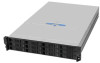
drives. Figure 1 shows a front view of the Intel® Storage System SSR212CC while Figure 2 depicts a rear view with the lid removed, showing those areas accessible to service personnel only. TP01828 Figure 1. Intel® Storage System SSR212CC - Front View Intel® Storage System SSR212CC User Guide 1 - Intel SSR212CC | User Guide - Page 20
D TP01857 Figure 2. Intel® Storage System SSR212CC - Rear View Showing Service Areas A. Riser Card Assembly B. Processor Air Duct C. Server Board D. Power Supply Cage E. Cooling Module The Enclosure Core Product The Intel® Storage System SSR212CC design concept is based on a sub-system together with - Intel SSR212CC | User Guide - Page 21
SRCS28X F. Intel® RAID Controller SRCS28X G. Empty slot H. ID LED I. USB Port J. Video Port K. NIC2 Port (1 GB) L. NIC1 Port (1 GB) M. Serial Port N. PS2 Keyboard Port O. Reset Button P. Blanking Plate Q. Power Supply Module Indicator LED G TP01824 Intel® Storage System SSR212CC User Guide 3 - Intel SSR212CC | User Guide - Page 22
in SATA disk drive in its carrier module. At the rear, the chassis assembly accommodates a power supply cage, a server board, and a PCI riser card assembly. A cover on the enclosure provides access to the cooling module and the server board subsystem. 4 Intel® Storage System SSR212CC User Guide - Intel SSR212CC | User Guide - Page 23
An Intel® Server Board SE7520JR2 with a single low-voltage Intel® Xeon® processor • An Intel® Management Module Professional • Two Intel® RAID Controller SRCS28X cards • Dual Intel® 10/100/1000 LAN ports Power Supply Module The Intel® Storage System SSR212CC ships with one 500-W power supply module - Intel SSR212CC | User Guide - Page 24
supply modules fitted in the power supply enclosure, providing dual-power sources for the system so that if one power supply module fails the other maintains the power supply and enclosure operation is not affected while the faulty unit is replaced. 6 Intel® Storage System SSR212CC User Guide - Intel SSR212CC | User Guide - Page 25
[Back pressure created by rack doors and obstacles not to exceed 5 pascals (0.5-mm water gauge)]. The cooling system provides sufficient capacity to ensure that drive maximum temperatures are not exceeded at 35°C ambient with one fan failed at 7,000 ft. Intel® Storage System SSR212CC User Guide 7 - Intel SSR212CC | User Guide - Page 26
the drive carrier to the drive bay to prevent accidental removal. The front cap also supports an ergonomic handle, which provides the following functions: • Spring loading of drive carrier into operates Continuous amber light indicates a failure condition 8 Intel® Storage System SSR212CC User Guide - Intel SSR212CC | User Guide - Page 27
system with ANY modules missing will disrupt the airflow and the drives will not receive sufficient cooling. Front Panel The front panel provides visibility access to three LEDs. A B ID C TP01833 Figure 10. Front Panel A. Power LED B. Fault LED C. ID LED Intel® Storage System SSR212CC User Guide - Intel SSR212CC | User Guide - Page 28
2U three-slot active PCI-X riser for Intel® RAID Controller SRCS28X Intel® RAID Controller SRCS28X Battery backup unit for Intel® RAID Controller SRCS28X 500-W power supply Intel® Management Module Professional for Intel® Server Board SE7520JR2 10 Intel® Storage System SSR212CC User Guide - Intel SSR212CC | User Guide - Page 29
Upgrades This chapter provides instructions for removing, installing, and replacing storage system components in your Intel® Storage System SSR212CC. Caution: When connecting the Intel® Storage System SSR212CC to a power source, use either the power cords that shipped with the system, or match the - Intel SSR212CC | User Guide - Page 30
storage system installation, review the configuration requirements listed in Table 3 for the Intel® Storage System SSR212CC. Table 3. Configuration Requirements Module Location Drive Bays Power Supply are available for fitting in unused drive bays. 12 Intel® Storage System SSR212CC User Guide - Intel SSR212CC | User Guide - Page 31
the maximum operating ambient temperature for the storage system, which is 35°C. • The rack should have a safe electrical distribution system. It must provide over- current protection for the storage system and must not be overloaded by the total Intel® Storage System SSR212CC User Guide 13 - Intel SSR212CC | User Guide - Page 32
to the Rail Kit Install Guide: Intel® Storage System SSR212MA/Intel® Storage System SSR212CC supplied with the rack mounting rail kit for assembly details. Removing or Installing the Enclosure Cover Warning: The enclosure cover must only be removed by a service personnel. Potential hazards include - Intel SSR212CC | User Guide - Page 33
on the palm latch (see letter "B") and slide the enclosure cover back (see letter "C") until it stops (about 2 inches). A C B Figure 12. Unlatching Enclosure Cover TP01826 Intel® Storage System SSR212CC User Guide 15 - Intel SSR212CC | User Guide - Page 34
cover to the chassis by tightening the lock a quarter turn until the close lock symbol aligns with the notch on the cover (see letter "C"). 16 Intel® Storage System SSR212CC User Guide - Intel SSR212CC | User Guide - Page 35
unused righthand slot and lower AC input socket. Operation of the storage system with ANY modules missing will disrupt airflow and the drives will not receive sufficient cooling. It is ESSENTIAL that all apertures are filled before operating the system. Intel® Storage System SSR212CC User Guide 17 - Intel SSR212CC | User Guide - Page 36
non-redundant power supply systems only, power down the storage system. See the Intel® Storage System Software User's Manual for instructions on powering down the system. 3. Remove the AC power cable from the failed power supply module. The top AC connector is for the left power supply. The bottom - Intel SSR212CC | User Guide - Page 37
instructions: 1. Observe all safety and ESD precautions listed in Appendix D, "Safety Information". 2. (For replacing a power supply module only) Remove the failed power supply module. For instructions, see "Removing a Power Supply Module" on page 18. Intel® Storage System SSR212CC User Guide - Intel SSR212CC | User Guide - Page 38
power supply cage (see letter "B") until it clicks into place. A B TP01849 Figure 18. Inserting Power Supply Module 5. Plug in the AC power cable to the new power supply module. 6. On non-redundant power supply systems, power up the storage system. 20 Intel® Storage System SSR212CC User Guide - Intel SSR212CC | User Guide - Page 39
each power supply module (see letter "B") indicates whether AC mains power is present. Caution: The power connections must always be disconnected prior to removal of the power supply unit from the enclosure. A B Figure 19. Connecting Power Cords TP01850 Intel® Storage System SSR212CC User Guide - Intel SSR212CC | User Guide - Page 40
, see "Removing the Enclosure Cover" on page 14. 5. Remove the cooling module. For instructions, see "Removing the Cooling Module" on page 51. 6. Remove the processor air duct. For instructions, see "Removing the Processor Air Duct" on page 72. 22 Intel® Storage System SSR212CC User Guide - Intel SSR212CC | User Guide - Page 41
20. Disconnecting First SATA Cable 8. Lift up on latch (see letter "A" in the following figure) and disconnect the main power (P1) cable from the server board (see letter "B"). A B TP02045 Figure 21. Disconnecting Main Power (P1) Cable from Server Board Intel® Storage System SSR212CC User Guide 23 - Intel SSR212CC | User Guide - Page 42
and lift the assembly out of the chassis (see letter "B"). Guide the SATA cables so that they clear the opening in the cross bar. Lay the PCI riser assembly on an anti-static surface. A A B TP02043 Figure 23. Removing PCI Riser Assembly from Chassis 24 Intel® Storage System SSR212CC User Guide - Intel SSR212CC | User Guide - Page 43
and sliding the assembly downwards until the riser card mates with the connector on the server board. The latches should lock into position once the PCI riser assembly is seated properly. TP02055 Figure 24. Installing PCI Riser Assembly into Chassis Intel® Storage System SSR212CC User Guide 25 - Intel SSR212CC | User Guide - Page 44
to its connector on the server board (see letter "A" in the following figure). When properly seated, the latch on the top of the connector (see letter "B") should lock the connector into position. B A TP02053 Figure 26. Connecting Main Power Cable 26 Intel® Storage System SSR212CC User Guide - Intel SSR212CC | User Guide - Page 45
instructions, see "Installing the Processor Air Duct" on page 73. 11. Install the enclosure cover. For instructions, see "Installing the Enclosure Cover" on page 16. 12. Re-connect all peripheral devices and the AC power cable. Power up the storage system. Intel® Storage System SSR212CC User Guide - Intel SSR212CC | User Guide - Page 46
old PCI riser connector card from the PCI riser assembly (see letter "B"). B A TP02063 Figure 28. Removing PCI Riser Connector Card from PCI Riser Assembly 28 Intel® Storage System SSR212CC User Guide - Intel SSR212CC | User Guide - Page 47
instructions, see "Installing the PCI Riser Assembly" on page 25. 11. Install the enclosure cover. For instructions, see "Installing the Enclosure Cover" on page 16. 12. Re-connect all peripheral devices and the AC power cable. Power up the storage system. Intel® Storage System SSR212CC User Guide - Intel SSR212CC | User Guide - Page 48
Caution: Before performing any maintenance on the system, back up the data. Follow the instructions in the operating system manual for shutting down the system. Caution: Refer to the support site at http://www.intel.com/support/motherboards/server/ssr212ma for the appropriate firmware version to - Intel SSR212CC | User Guide - Page 49
the Intel® RAID Controller to the PCI riser assembly (see letter "B"). Detach the Intel® RAID Controller from its connector on the PCI riser assembly (see letter "C"). C B A TP02062 Figure 31. Removing Intel® RAID Controller from PCI Riser Assembly Intel® Storage System SSR212CC User Guide 31 - Intel SSR212CC | User Guide - Page 50
into the chassis. For instructions, see "Installing the PCI Riser Assembly" on page 25. 13. Install the enclosure cover. For instructions, see "Installing the Enclosure Cover" on page 16. 14. Re-connect all peripheral devices and the AC power cable. 32 Intel® Storage System SSR212CC User Guide - Intel SSR212CC | User Guide - Page 51
Caution: Before performing any maintenance on the system, back up the data. Follow the instructions in the operating system manual for shutting down the system. Caution: Refer to the support site at http://www.intel.com/support/motherboards/server/ssr212cc for the appropriate firmware version to use - Intel SSR212CC | User Guide - Page 52
Upgrades 9. Align and seat the battery backup unit in its connector on the Intel® RAID Controller. Secure the battery backup unit to theIntel® RAID Controller with three screws. TP02341 Figure 34. Attaching Battery Backup Unit to Intel® RAID Controller 34 Intel® Storage System SSR212CC User Guide - Intel SSR212CC | User Guide - Page 53
properly seat the Intel® RAID Controller in the slot. TP02342 Figure 35. Installing Intel® RAID Controller 11. Attach the extended battery cable to the battery of the card being replaced. TP02343 Figure 36. Attaching Extended Battery Cable to Battery Intel® Storage System SSR212CC User Guide 35 - Intel SSR212CC | User Guide - Page 54
into the chassis. For instructions, see "Installing the PCI Riser Assembly" on page 25. 14. Install the enclosure cover. For instructions, see "Installing the Enclosure Cover" on page 16. 15. Re-connect all peripheral devices and the AC power cable. 36 Intel® Storage System SSR212CC User Guide - Intel SSR212CC | User Guide - Page 55
New Battery Backup Unit 5. Turn off all peripheral devices connected to the storage system. Turn off the storage system. 6. Disconnect the AC power cord(s). 7. Remove the enclosure cover. For instructions, see "Removing the Enclosure Cover" on page 14. Intel® Storage System SSR212CC User Guide 37 - Intel SSR212CC | User Guide - Page 56
Hardware Installations and Upgrades 8. Remove the PCI riser assembly. For instructions, see "Removing the PCI Riser Assembly" on page 22. 9. With the top side of the PCI to the battery holder. TP02332 Figure 41. Removing Old Battery from Battery Holder 38 Intel® Storage System SSR212CC User Guide - Intel SSR212CC | User Guide - Page 57
Hardware Installations and Upgrades 11. Secure the new battery to the battery holder with two screws. TP02334 Figure 42. Securing New Battery to Battery Holder Intel® Storage System SSR212CC User Guide 39 - Intel SSR212CC | User Guide - Page 58
with four screws. TP02337 Figure 43. Re-attaching Battery Holder to PCI Riser Assembly 13. Remove the Intel® RAID Controller with the bad battery from the PCI Riser Assembly. For instructions, see "Removing an Intel® RAID Controller" on page 30. 40 Intel® Storage System SSR212CC User Guide - Intel SSR212CC | User Guide - Page 59
the card. TP02338 Figure 44. Detaching Bad Battery Backup Unit from Intel® RAID Controller 15. Disconnect the extended battery cable from the bad battery backup unit. TP02339 Figure 45. Disconnecting Extended Battery Cable from Battery Backup Unit Intel® Storage System SSR212CC User Guide 41 - Intel SSR212CC | User Guide - Page 60
Controller with three screws. TP02341 Figure 47. Attaching New Battery Backup Unit to Intel® RAID Controller 18. Install the Intel® RAID Controller into the PCI riser assembly. For instructions, see "Installing an Intel® RAID Controller" on page 33. 42 Intel® Storage System SSR212CC User Guide - Intel SSR212CC | User Guide - Page 61
the Processor Air Duct" on page 72. 6. Unlatch the two levers (see letter "A" in the following figure) on the PCI riser assembly and lift the assembly out of the chassis (see letter "B"). A A B TP02043 Figure 48. Removing PCI Riser Assembly from Chassis Intel® Storage System SSR212CC User Guide - Intel SSR212CC | User Guide - Page 62
Hardware Installations and Upgrades 7. Lay the PCI riser assembly upside down across the corner of the chassis. Take care not to unnecessarily pinch the SATA cables. Remove the PCI slot filler. Figure 49. Removing PCI Slot Filler AF000563 44 Intel® Storage System SSR212CC User Guide - Intel SSR212CC | User Guide - Page 63
Hardware Installations and Upgrades 8. Refer to the manufacturer's manual that shipped with the PCI card to configure any necessary jumper settings. Align the PCI in the previous step. Figure 50. Installing PCI Card into PCI Riser Assembly AF000564 Intel® Storage System SSR212CC User Guide 45 - Intel SSR212CC | User Guide - Page 64
on the server board. Ensure Processor Air Duct" on page 73. 11. Re-install the enclosure cover. For instructions, see "Installing the Enclosure Cover" on page 16. 12. Re-connect all peripheral devices and the AC power cable. Power up the storage system. 46 Intel® Storage System SSR212CC User Guide - Intel SSR212CC | User Guide - Page 65
module is located centrally within the enclosure, installed between the drive bays and the server board. Hot Swap Replacing the Cooling Module 1. Observe all safety and ESD cooling module. A C B TP01851 Figure 52. Accessing the Cooling Module Intel® Storage System SSR212CC User Guide 47 - Intel SSR212CC | User Guide - Page 66
following figure). Caution: The cooling module must be replaced within 30 seconds to ensure the system does not overheat and shut down. A TP01852 Figure 53. Opening Cooling Module Latches TP01780 Figure 54. Cooling Module with Latches in Open Position 48 Intel® Storage System SSR212CC User Guide - Intel SSR212CC | User Guide - Page 67
the two latches in the open position, slide the old cooling module out of the enclosure. TP01780 TP01858 Figure 56. Removing Cooling Module from Chassis Intel® Storage System SSR212CC User Guide 49 - Intel SSR212CC | User Guide - Page 68
seconds. TP01780 TP01859 Figure 57. Installing the Cooling Module 7. Cam the replacement (new) cooling module home by manually closing the latches. A click should be heard as the latches engage. TP01861 Figure 58. Latching Cooling Module into Chassis 50 Intel® Storage System SSR212CC User Guide - Intel SSR212CC | User Guide - Page 69
manual for shutting down the system. 1. Observe all safety and ESD precautions listed in Appendix D, "Safety Information". 2. Turn off all peripheral devices connected to the storage system. Turn off the storage system. 3. Disconnect the AC power cord(s). Intel® Storage System SSR212CC User Guide - Intel SSR212CC | User Guide - Page 70
cover back (see letter "C") until it stops (about 2 inches), revealing the mounting brackets for the cooling module. A C B TP01851 Figure 60. Accessing the Cooling Module 52 Intel® Storage System SSR212CC User Guide - Intel SSR212CC | User Guide - Page 71
Module 6. With the two latches in the open position, slide the old cooling module out of the enclosure. TP01780 Figure 62. Removing Cooling Module TP01858 Intel® Storage System SSR212CC User Guide 53 - Intel SSR212CC | User Guide - Page 72
maintenance on the system, back up the data. Follow the instructions in the operating system manual for shutting down the system. Warning: Your storage system cannot run without the cooling module. A C B TP01851 Figure 63. Accessing the Cooling Module 54 Intel® Storage System SSR212CC User Guide - Intel SSR212CC | User Guide - Page 73
"A" in the following figure) on the cooling module. A TP01852 Figure 64. Opening Cooling Module Latches TP01780 Figure 65. Cooling Module with Latches in Open Position Intel® Storage System SSR212CC User Guide 55 - Intel SSR212CC | User Guide - Page 74
latches engage automatically. TP01780 TP01859 Figure 66. Inserting Cooling Module into Chassis 5. Cam the module home by manually closing the latches. A click should be heard as the latches engage. TP01861 Figure 67. Closing Latches on Cooling Module 56 Intel® Storage System SSR212CC User Guide - Intel SSR212CC | User Guide - Page 75
off the storage system. 3. Disconnect the AC power cord(s). 4. Remove the enclosure cover. For instructions, see "Removing the Enclosure Cover" on page 14. 5. Remove the cooling module. For instructions, see "Removing the Cooling Module" on page 51. Intel® Storage System SSR212CC User Guide 57 - Intel SSR212CC | User Guide - Page 76
Hardware Installations and Upgrades 6. Disconnect the IPMB cable from the old fan interposer board (see letter "A" in the following figure). A TP01868 Figure 68. Disconnecting IPMB Cable from Fan Interposer Board 58 Intel® Storage System SSR212CC User Guide - Intel SSR212CC | User Guide - Page 77
board (see letter "B") from its connector on the backplane. Caution: Do not operate your storage system without a functioning fan interposer board installed in the system. B A A A TP02007 Figure 69. Removing Fan Interposer Board from Chassis Intel® Storage System SSR212CC User Guide 59 - Intel SSR212CC | User Guide - Page 78
following figure). Secure the fan interposer board to the chassis with three screws (see letter "B"). A B B B TP02009 Figure 70. Securing Fan Interposer Board to Chassis 60 Intel® Storage System SSR212CC User Guide - Intel SSR212CC | User Guide - Page 79
For instructions, see "Installing the Cooling Module" on page 54. 11. Install the enclosure cover. For instructions, see "Installing the Enclosure Cover" on page 16. 12. Re-connect all peripheral devices and the AC power cable. Power up the storage system. Intel® Storage System SSR212CC User Guide - Intel SSR212CC | User Guide - Page 80
your Intel® Storage System SSR212CC. Refer to "Planning Your Installation" on page 11 for information on your overall system configurations. Removing a Drive Carrier Caution: Before performing any maintenance on the system, back up the data. Follow the instructions in the operating system manual for - Intel SSR212CC | User Guide - Page 81
manual for shutting down the system. Caution: An empty drive carrier MUST be fitted in ALL unused drive bays.There will be inadequate drive cooling if any drive bays are left open. 1. Observe all safety and ESD precautions listed in Appendix D, "Safety Information" Intel® Storage System SSR212CC - Intel SSR212CC | User Guide - Page 82
is orientated so that the drive is uppermost and the handle opens from the left. B C D E A Figure 74. Installing Drive Carrier into Drive Bay TP01832 64 Intel® Storage System SSR212CC User Guide - Intel SSR212CC | User Guide - Page 83
a hard drive into a drive carrier. If not replacing the hard drive, ensure that a blank drive carrier is fitted in the drive bay. 5. For instructions on re-installing the drive carrier into the drive bay, see "Installing a Drive Carrier" on page 63. Intel® Storage System SSR212CC User Guide 65 - Intel SSR212CC | User Guide - Page 84
the hard drive to the drive carrier with four screws (see letter "B"). A B TP01829 Figure 76. Installing Hard Drive in Drive Carrier 5. For instructions on re-installing the drive carrier into the drive bay, see "Installing a Drive Carrier" on page 63. 66 Intel® Storage System SSR212CC User Guide - Intel SSR212CC | User Guide - Page 85
. For instructions, see "Removing the PCI Riser Assembly" on page 22. 8. Remove the heat sink and processor. For instructions, see "Removing the Processor" on page 74. 9. Remove the memory DIMMs. For instructions, see "Removing DIMMs" on page 91. Intel® Storage System SSR212CC User Guide 67 - Intel SSR212CC | User Guide - Page 86
Disconnect the reset (see letter "D") and power switch (see letter "E") cables. B D C E A TP02010 Figure 77. Disconnecting Cables from Server Board 11. Remove the IMM Pro module. For instructions, see "Removing the IMM Pro Module" on page 94. 68 Intel® Storage System SSR212CC User Guide - Intel SSR212CC | User Guide - Page 87
Hardware Installations and Upgrades 12. Remove the seven screws securing the server board to the chassis. Remove server board from chassis and store in an anti-static bag. TP02012 Figure 78. Removing Server Board from Chassis Intel® Storage System SSR212CC User Guide 69 - Intel SSR212CC | User Guide - Page 88
in the chassis. TP02012 Figure 79. Installing Server Board in Chassis 2. Install the processor and heatsink. For instructions, see "Installing the Processor" on page 76. 3. Install the memory DIMMs. For instructions, see "Installing DIMMs" on page 93. 70 Intel® Storage System SSR212CC User Guide - Intel SSR212CC | User Guide - Page 89
the cooling module. For instructions, see "Installing the Cooling Module" on page 54. 9. Install the enclosure cover. For instructions, see "Installing the Enclosure Cover" on page 16. 10. Re-connect all peripheral devices and the AC power cable. Intel® Storage System SSR212CC User Guide 71 - Intel SSR212CC | User Guide - Page 90
Enclosure Cover" on page 14. 5. Lift the processor air duct from its location over the processor socket(s). TP01856 Figure 81. Removing Processor Air Duct 6. If removing a processor air duct as part of another procedure, continue with that procedure. 72 Intel® Storage System SSR212CC User Guide - Intel SSR212CC | User Guide - Page 91
connected to the storage system. 3. Disconnect the AC power cord(s). 4. Remove the enclosure cover. For instructions, see "Removing the Enclosure Cover" on page 14. 5. Install the processor air duct. TP01855 Figure 82. Installing Processor Air Duct Intel® Storage System SSR212CC User Guide 73 - Intel SSR212CC | User Guide - Page 92
the storage system. 3. Disconnect the AC power cord(s). 4. Remove the enclosure cover. For instructions, see "Removing the Enclosure Cover" on page 14. 5. Remove the processor air duct. For instructions, see "Removing the Processor Air Duct" on page 72. 74 Intel® Storage System SSR212CC User Guide - Intel SSR212CC | User Guide - Page 93
it does not pull up easily, twist the heatsink again. Caution: Do not force the heatsink from the processor. Doing so could damage the processor. TP01775 Figure 83. Removing Heatsink 7. Lift the processor lever. TP01776 Figure 84. Opening Socket Lever Intel® Storage System SSR212CC User Guide 75 - Intel SSR212CC | User Guide - Page 94
the storage system. 3. Disconnect the AC power cord(s). 4. Remove the enclosure cover. For instructions, see "Removing the Enclosure Cover" on page 14. 5. Remove the processor air duct. For instructions, see "Removing the Processor Air Duct" on page 72. 76 Intel® Storage System SSR212CC User Guide - Intel SSR212CC | User Guide - Page 95
Socket Lever 7. Align the pins of the processor with the socket, and insert the processor into the socket. Note: Make sure the alignment triangle mark and the alignment triangle cut-out align correctly. A B A TP00764 Figure 87. Inserting Processor Intel® Storage System SSR212CC User Guide 77 - Intel SSR212CC | User Guide - Page 96
not damage the TIM. 10. Set the heatsink over the processor, lining up the four captive screws with the four posts surrounding the processor. Loosely screw in the captive screws on the heatsink corners in . TP00774 Figure 89. Installing the Heatsink 78 Intel® Storage System SSR212CC User Guide - Intel SSR212CC | User Guide - Page 97
, see "Removing the Cooling Module" on page 51. 6. Remove the processor air duct. For instructions, see "Removing the Processor Air Duct" on page 72. 7. Remove the PCI riser assembly. For instructions, see "Removing the PCI Riser Assembly" on page 22. Intel® Storage System SSR212CC User Guide 79 - Intel SSR212CC | User Guide - Page 98
Disconnect the IPMB cable (see letter "B"). Disconnect the P3 power supply signal cable (see letter "C"). Disconnect the reset (see letter "D") and power switch (see letter "E") cables. B DC E AF00571 A Figure 90. Disconnecting Cables from Server Board 80 Intel® Storage System SSR212CC User Guide - Intel SSR212CC | User Guide - Page 99
the seven screws securing the server board to the chassis. Remove the server board. TP02012 Figure 91. Installing Server Board in Chassis 10. Bay Numbering Order 11. Remove all drive carriers. For instructions, see "Removing a Drive Carrier" on page 62. Intel® Storage System SSR212CC User Guide 81 - Intel SSR212CC | User Guide - Page 100
and Upgrades Note: The following steps are performed on the replacement chassis. 12. Install the server board by aligning the screw holes in the server board with the standoffs in the new chassis. TP02012 Figure 93. Installing Server Board in Chassis 82 Intel® Storage System SSR212CC User Guide - Intel SSR212CC | User Guide - Page 101
figure). Connect the IPMB cable (see letter "B"). Connect the P3 power supply signal cable (see letter "C"). Connect the reset (see letter "D") and power switch (see letter "E") cables. B DC E AF00571 A Figure 94. Connecting Cables to Server Board Intel® Storage System SSR212CC User Guide 83 - Intel SSR212CC | User Guide - Page 102
are installed in the proper order. 1 2 3 4 5 6 7 8 9 10 11 12 TP01831 Figure 96. Drive Bay Numbering Order 20. Re-connect all peripheral devices and the AC power cable. Power up the storage system. 84 Intel® Storage System SSR212CC User Guide - Intel SSR212CC | User Guide - Page 103
the storage system. 3. Disconnect the AC power cord(s). 4. Remove the enclosure cover. For instructions, see "Removing the Enclosure Cover" on page 14. 5. Remove the processor air duct. For instructions, see "Removing the Processor Air Duct" on page 72. Intel® Storage System SSR212CC User Guide 85 - Intel SSR212CC | User Guide - Page 104
against the sheet metal of the chassis. Place a support underneath the PCI riser assembly, next to the chassis and workbench, to minimize the stress on the cables (see letter "D"). A A B C D TP00879 Figure 97. Removing PCI Riser Assembly from Chassis 86 Intel® Storage System SSR212CC User Guide - Intel SSR212CC | User Guide - Page 105
its socket. TP00760 Figure 98. Removing Server Board Battery 8. Dispose of the battery according to local ordinance. 9. Remove the new lithium battery from its package, and, being careful to observe the correct polarity, insert it in the battery socket. Intel® Storage System SSR212CC User Guide 87 - Intel SSR212CC | User Guide - Page 106
, see "Installing the Processor Air Duct" on page 73. 12. Install the enclosure cover. For instructions, see "Installing the Enclosure Cover" on page 16. 13. Re-connect all peripheral devices and the AC power cable. Power up the storage system. 88 Intel® Storage System SSR212CC User Guide - Intel SSR212CC | User Guide - Page 107
2B, and 3B. Refer to the Tested Memory List at http://www.intel.com/support/motherboards/server/ssr212cc/ for the current list of supported memory. If six DIMMs are installed, the following maximum populated DIMMs must meet the following requirements: Intel® Storage System SSR212CC User Guide 89 - Intel SSR212CC | User Guide - Page 108
. • Four DIMMs are used with identical single-ranked DIMMs in banks 2 and 3. DIMMs in sockets 1A and 1B must be dual-ranked and identical. 90 Intel® Storage System SSR212CC User Guide - Intel SSR212CC | User Guide - Page 109
the storage system. 3. Disconnect the AC power cord(s). 4. Remove the enclosure cover. For instructions, see "Removing the Enclosure Cover" on page 14. 5. Remove the processor air duct. For instructions, see "Removing the Processor Air Duct" on page 72. Intel® Storage System SSR212CC User Guide 91 - Intel SSR212CC | User Guide - Page 110
, see "Installing the Processor Air Duct" on page 73. 10. Install the enclosure cover. For instructions, see "Installing the Enclosure Cover" on page 16. 11. Re-connect all peripheral devices and the AC power cable. Power up the storage system. 92 Intel® Storage System SSR212CC User Guide - Intel SSR212CC | User Guide - Page 111
place. Make sure the clips are latched firmly in place. DIMM 2A DIMM 3B DIMM 3A DIMM 2B DIMM 1A DIMM 1B Figure 102. Installing Memory TP00761 Intel® Storage System SSR212CC User Guide 93 - Intel SSR212CC | User Guide - Page 112
with the appropriate firmware version. Refer to the Intel® Storage System SSR212CC Tested Hardware and Operating System List for the tested firmware version. Refer to the support site at http://www.intel.com/support/ motherboards/server/ism for the appropriate firmware and documentation to download - Intel SSR212CC | User Guide - Page 113
against the sheet metal of the chassis. Place a support underneath the PCI riser assembly, next to the chassis and workbench, to minimize the stress on the cables (see letter "D"). A A B C D TP00879 Figure 103. Removing PCI Riser Assembly from Chassis Intel® Storage System SSR212CC User Guide 95 - Intel SSR212CC | User Guide - Page 114
and slightly raise the IMM Pro module to disengage the stand-off from the server board. To avoid damage to the connector, do not lift the edge of Server Board 7. If removing the IMM Pro module as part of another procedure, continue with that procedure. 96 Intel® Storage System SSR212CC User Guide - Intel SSR212CC | User Guide - Page 115
the riser card mates with the connector on the server board. The latches should lock into position once instructions, see "Installing the Enclosure Cover" on page 16. 10. Re-connect all peripheral devices and the AC power cable. Power up the storage system. Intel® Storage System SSR212CC User Guide - Intel SSR212CC | User Guide - Page 116
www.intel.com/ support/motherboards/server/ssr212cc for the appropriate firmware to use. 1. Observe all safety and ESD precautions listed in Appendix D, "Safety Information". 2. Turn off all peripheral devices connected to the storage system. Turn off the storage system. 3. Disconnect the AC power - Intel SSR212CC | User Guide - Page 117
Chassis 6. If not already present, attach the nylon stand-off to the IMM Pro module. TP02344 Figure 107. Securing IMM Pro Module Stand-off to Server Board Intel® Storage System SSR212CC User Guide 99 - Intel SSR212CC | User Guide - Page 118
until the module seats itself in the connector (see letter "B") on the server board. A B TP01867 Figure 108. Installing IMM Pro Module to Server Board 8. If installing the IMM Pro module as part of another procedure, continue with that procedure. 100 Intel® Storage System SSR212CC User Guide - Intel SSR212CC | User Guide - Page 119
the riser card mates with the connector on the server board. The latches should lock into position once instructions, see "Installing the Enclosure Cover" on page 16. 11. Re-connect all peripheral devices and the AC power cable. Power up the storage system. Intel® Storage System SSR212CC User Guide - Intel SSR212CC | User Guide - Page 120
Hardware Installations and Upgrades 102 Intel® Storage System SSR212CC User Guide - Intel SSR212CC | User Guide - Page 121
to the following table for conditions of the power supply module LED. Table 5. Power Supply Module LED Indicators Power Supply Condition No AC power to all power supply modules No AC power to this power supply module only Intel® Storage System SSR212CC User Guide Power Supply LED OFF Amber 103 - Intel SSR212CC | User Guide - Page 122
lit when booting up the system. The blue system identification LED is used to help identify a system for servicing. This is especially useful when the system is installed in a high-density rack or cabinet that is populated with several similar systems. 104 Intel® Storage System SSR212CC User Guide - Intel SSR212CC | User Guide - Page 123
• In the event of a system failure or hang condition that prevents you from powering down the system via the Intel® Storage System Console, do the following: Hold down the Power button for approximately 3 seconds OR Remove AC mains at the power source. Intel® Storage System SSR212CC User Guide 105 - Intel SSR212CC | User Guide - Page 124
Operation 106 Intel® Storage System SSR212CC User Guide - Intel SSR212CC | User Guide - Page 125
4 Troubleshooting and Problem Solving Overview The Intel® Storage System SSR212CC enclosure includes an enclosure services processor and associated monitoring and control logic to enable it to diagnose problems within the enclosure's power, cooling and drive systems. The sensors for power and - Intel SSR212CC | User Guide - Page 126
Status Fault Status Power Fault ID Green On On Amber Off On Blue N/A N/A Troubleshooting The following sections describe common problems, with possible solutions, which can occur with your Intel® Storage System SSR212CC. Refer to the Intel® Server Board SE7520JR2 User Guide for additional - Intel SSR212CC | User Guide - Page 127
Troubleshooting and Problem Solving Power Supply Module Faults Symptom 1. Front Panel FAULT LED amber Cause 1. Any power fault Action 1. Check that he AC mains connection to power supply/unit is live. Thermal Control The Intel® Storage System SSR212CC enclosure uses extensive thermal monitoring - Intel SSR212CC | User Guide - Page 128
Troubleshooting and Problem exiting power supply unit problem before continuing. Thermal Shutdown Important: An enclosure will shut down when a critical temperature threshold is exceeded in order to prevent permanent damage to the disk drives. 110 Intel® Storage System SSR212CC User Guide - Intel SSR212CC | User Guide - Page 129
must be fitted with a drive carrier or a blank drive carrier in order to maintain a balanced airflow. • All power supply module(s), electronics modules and/or blank plates must be in place for the air to flow correctly throughout the storage system. Intel® Storage System SSR212CC User Guide 111 - Intel SSR212CC | User Guide - Page 130
Troubleshooting and Problem Solving 112 Intel® Storage System SSR212CC User Guide - Intel SSR212CC | User Guide - Page 131
Range Selection Frequency Inrush Current Power Factor Corrections Harmonics Output Rails Dimensions 100 - 240 VAC rated Full Range power supply unit 50/60 Hz 50A @ 260VAC 95%@110V full load Meets EN61000-3-2 6 84 mm high x 101 mm wide x 300 mm long Intel® Storage System SSR212CC User Guide 113 - Intel SSR212CC | User Guide - Page 132
Power Supply Safety and EMC Compliance Safety Compliance EMC Compliance UL 60950 IEC 60950 EN 60950 CFR47 Part 15B Class A EN55022 EN55024 Power Cord Important: The plug and the complete power Harmonized, H05-VVF-3G1.0 IEC 320, C-13, 250V, 10A. 114 Intel® Storage System SSR212CC User Guide - Intel SSR212CC | User Guide - Page 133
for each fan Operated from resettable fused 12V from supply rail Operational Temperature Range 5°C to 35°C Non-Operational 1°C to +50°C Storage 1°C to +60°C Shipping -40°C to +60 ) 30g 10ms 1/2 sine (test without drives) 0.2grms 5-500 Hz Random Intel® Storage System SSR212CC User Guide 115 - Intel SSR212CC | User Guide - Page 134
Dimensions Weight Transition Card Operating Temperature Power Dissipation Height 26.6 mm Width 106.5 mm Depth 220.2 mm 0.8 kg (1.0" 300Gb drive) Mounting locations for ATA - SATA drives with transition card attached 5° C to 35° C 14 Watts maximum 116 Intel® Storage System SSR212CC User Guide - Intel SSR212CC | User Guide - Page 135
Intel® Server Board SE7520JR2, execute the following steps to ensure that the server board has the correct BIOS settings: 1. Connect a VGA monitor, keyboard and mouse to the storage system. 2. Power up the storage system Disabled Disabled Enabled Intel® Storage System SSR212CC User Guide 117 - Intel SSR212CC | User Guide - Page 136
Intel® Server Board SE7520JR2 BIOS Settings 118 Intel® Storage System SSR212CC User Guide - Intel SSR212CC | User Guide - Page 137
the operating system; however, RAID 0 usually denotes two or more drives. RAID 0 RAID Adapter ABCDEF Available Capacity N=# disks C = Disk Capacity Available Capacity = N*C A B C D E F Data Striping RAID 0 Figure 111. RAID 0 - Data Striping Intel® Storage System SSR212CC User Guide 119 - Intel SSR212CC | User Guide - Page 138
, the response time is very good. RAID 5 is particularly suitable for systems with medium to large capacity requirements, due to the efficient ratio of installed Striping & Striped Parity RAID 5 Figure 113. RAID 5 - Data Striping with Striped Parity 120 Intel® Storage System SSR212CC User Guide - Intel SSR212CC | User Guide - Page 139
RAID Adapter ABCDEF Available Capacity N=# disks C = Disk Capacity Available Capacity = (N*C) /2 A A C C E E B B D D F F Disk Mirror & Data Striping RAID 10 Figure 114. RAID 10 - Combination of RAID 1 and RAID 0 Intel® Storage System SSR212CC User Guide 121 - Intel SSR212CC | User Guide - Page 140
Available Capacity N=# disks C = Disk Capacity Available Capacity = (N*C)(N-1) /N A E P(I+K) C P(E+G) I P1(A+C) G K B F P(J+L) D P(F+H) J P1(B+D) H L RAID 5 & Data Striping RAID 50 Figure 115. RAID 50 - Combination of RAID 5 and RAID 0 122 Intel® Storage System SSR212CC User Guide - Intel SSR212CC | User Guide - Page 141
Firmware or the Server Board BIOS If replacing an Intel® Server Board SE7520JR2 or Intel® RAID Controller, refer to the support site at http://www.intel.com/support/motherboards/server/ssr212cc for downloading the appropriate firmware or BIOS. Intel® Storage System SSR212CC User Guide 123 - Intel SSR212CC | User Guide - Page 142
Upgrading Component Firmware 124 Intel® Storage System SSR212CC User Guide - Intel SSR212CC | User Guide - Page 143
in serious injury or death if safety instructions are not followed. Indicates hot components or surfaces. Indicates do not touch fan blades, may result in injury. Indicates to unplug all AC power cord(s) to disconnect AC power Please recycle battery Intel® Storage System SSR212CC User Guide 125 - Intel SSR212CC | User Guide - Page 144
the system AC power, 5V standby power is active whenever the system is plugged in. To remove power from system, you must unplug the AC power cord from the wall outlet. Your system may use more than one AC power cord. Make sure all AC power cords are 126 Intel® Storage System SSR212CC User Guide - Intel SSR212CC | User Guide - Page 145
accessing the inside of the product: • Turn off all peripheral devices connected to this product. • Turn off the system by pressing the power button to off. • Disconnect the AC power by unplugging all AC power cords from the system or wall outlet. Intel® Storage System SSR212CC User Guide 127 - Intel SSR212CC | User Guide - Page 146
the power supply. There are no serviceable parts in the power supply. Return to manufacturer for servicing. • Power down the server and disconnect all power from the server, place the board component side up on a grounded, static free surface. Use a 128 Intel® Storage System SSR212CC User Guide - Intel SSR212CC | User Guide - Page 147
radiation exposure and/or personal injury: • Do not open the enclosure of any laser peripheral or device • Laser peripherals or devices have are not user serviceable • Return to manufacturer for servicing Intel® Storage System SSR212CC User Guide 129 - Intel SSR212CC | User Guide - Page 148
des betreffenden Produkts hat die Produktdokumentation Vorrang. Die Integration und Wartung des Servers darf nur durch technisch qualifizierte Personen erfolgen. Um die Einhaltung der von der Netzspannung zu trennen. Bereiten Sie bitte Batterie auf 130 Intel® Storage System SSR212CC User Guide - Intel SSR212CC | User Guide - Page 149
Geräte erzeugt werden. • In gewittergefährdeten Gebieten sollten Sie das System an einen Überspannungsschutz anschließen und bei einem Gewitter die Telekommunikationskabel zum lassen, um das Gewicht zu reduzieren und die Handhabung zu erleichtern. Intel® Storage System SSR212CC User Guide 131 - Intel SSR212CC | User Guide - Page 150
, ziehen Sie dessen Netzkabel ab, bevor Sie es aus dem Server ausbauen. Zur Vermeidung von Stromschlägen schalten Sie den Server aus, und trennen Sie vor dem Öffnen des Geräts müssen an eine ordnungsgemäß geerdete Steckdose angeschlossen sein. 132 Intel® Storage System SSR212CC User Guide - Intel SSR212CC | User Guide - Page 151
das Gerät für Wartungsarbeiten an den Hersteller zurück. • Schalten Sie den Server aus, und ziehen Sie alle Netzkabel ab, bevor Sie Komponenten ein- oder Ihr System mit eine Lüfterabdeckung besitzt, darf es nicht ohne diese Abdeckung betrieben werden. Intel® Storage System SSR212CC User Guide 133 - Intel SSR212CC | User Guide - Page 152
Server mit der Bauelementseite nach oben auf eine geerdete, statisch entladene Unterlage.Verwenden Sie dazu, sofern verfügbar, eine leitfahige Schaumstoffunterlage, aber niche die Schutzhülle der Platine. Ziehen Sie die Platine nicht über eine Fläche. 134 Intel® Storage System SSR212CC User Guide - Intel SSR212CC | User Guide - Page 153
oder Laser- Komponenten. • Laser-Peripheriegeräte oder -Komponenten besitzen keine für den Benutzer wartungsbedürftigen Teile. • Schicken Sie das Gerät für Wartungsarbeiten an den Hersteller zurück. Intel® Storage System SSR212CC User Guide 135 - Intel SSR212CC | User Guide - Page 154
par des techniciens qualifiés. Vous devez suivre les informations de ce guide et les instructions d'assemblage des manuels de serveur pour vérifier et maintenir la conformit secteur pour déconnecter l'alimentation. Veuillez réutiliser la batterie 136 Intel® Storage System SSR212CC User Guide - Intel SSR212CC | User Guide - Page 155
autre assistance appropriée lorsque vous déplacez et soulevez le matériel. • Pour réduire le poids en vue de faciliter la manipulation, retirez tout composant amovible. Intel® Storage System SSR212CC User Guide 137 - Intel SSR212CC | User Guide - Page 156
Les cordons d'alimentation doivent répondre aux critères suivants : • Le cordon d'alimentation doit supporter une intensité supérieure à celle indiquée sur le produit. • Le cordon d'alimentation des prises électriques correctement reliées à la terre. 138 Intel® Storage System SSR212CC User Guide - Intel SSR212CC | User Guide - Page 157
. Si votre système est fourni avec une protection sur le ventilateur, ne mettez pas le système en route sans la protection en place. Intel® Storage System SSR212CC User Guide 139 - Intel SSR212CC | User Guide - Page 158
fixé à un support inamovible pour éviter qu'il ne bascule lors de l'extension d'un serveur ou d'un élément de l'équipement. Le rack doit être installé conformément aux instructions du fabricant. Installez ce que la carte ne glisse sur aucune surface. 140 Intel® Storage System SSR212CC User Guide - Intel SSR212CC | User Guide - Page 159
autres composants sont correctement installés. • Fixez les panneaux au châssis en suivant les instructions du produit. Périphériques laser Attention: Pour éviter tout risque d'exposition aux utilisateur. • Retournez-les au fabricant en cas de problème. Intel® Storage System SSR212CC User Guide 141 - Intel SSR212CC | User Guide - Page 160
ceñirse a las directrices de esta guía y a las instrucciones de montaje de los manuales del servidor para asegurar y mantener el cumplimiento con las certificaciones y homologaciones existentes de los la alimentación de CA Recicle por favor la batería 142 Intel® Storage System SSR212CC User Guide - Intel SSR212CC | User Guide - Page 161
sean adecuados al trasladar o levantar el equipo. • Para que el peso sea menor para manipularlo con más facilidad, extraiga los componentes que sean de fácil extracción. Intel® Storage System SSR212CC User Guide 143 - Intel SSR212CC | User Guide - Page 162
conexión en funcionamiento. Algunas fuentes de alimentación de electricidad de los servidores de Intel utilizan el polo neutral del fuselaje. Para evitar riesgos de choques electricos use efectuar de forma inmediata con el fin de desconectarlos. 144 Intel® Storage System SSR212CC User Guide - Intel SSR212CC | User Guide - Page 163
se le ha suministrado con una protección para el ventilador, asegúrese de que cuando esté funcionando el sistema la protección esté en su sitio. Intel® Storage System SSR212CC User Guide 145 - Intel SSR212CC | User Guide - Page 164
. Utilice una almohadilla de espuma conductora si dispone de ella, pero nunca el envoltorio de la tarjeta. No deslice la tarjeta sobre ninguna superficie. 146 Intel® Storage System SSR212CC User Guide - Intel SSR212CC | User Guide - Page 165
caja de ningún periférico o dispositivo láser • Los periféricos o dispositivos láser no pueden ser reparados por el usuario • Haga que el fabricante los repare. Intel® Storage System SSR212CC User Guide 147 - Intel SSR212CC | User Guide - Page 166
Safety Information 简体中文 Intel Intel Intel Web UL 注意 警告 148 Intel® Storage System SSR212CC User Guide - Intel SSR212CC | User Guide - Page 167
Safety Information ITE ITE 场地选择 注意事项 5V Intel® Storage System SSR212CC User Guide 149 - Intel SSR212CC | User Guide - Page 168
Safety Information 150 Intel® Storage System SSR212CC User Guide - Intel SSR212CC | User Guide - Page 169
Safety Information ESD) ESD ESD ESD ESD Intel® Storage System SSR212CC User Guide 151 - Intel SSR212CC | User Guide - Page 170
Safety Information 其他危险 替换电池 152 Intel® Storage System SSR212CC User Guide - Intel SSR212CC | User Guide - Page 171
is available at http:// support.intel.com/support/motherboards/server/ssr212cc/. For the fastest service, please submit your form via the Internet. Date Submitted Company Name Contact Name Email Address Intel Server Product Priority (Critical, Hot, High, Low Brief Problem Description. Provide - Intel SSR212CC | User Guide - Page 172
Driver Revision IRQ # I/O Base Address NIC X Peripheral Full-height Riser PCI Slot 1 PCI Slot 2 PCI Slot 3 Video On-board Video Add-in Video NIC On-Board NIC1 On-Board NIC2 Description Driver Revision IRQ I/O Base FW Address Revision 154 Intel® Storage System SSR212CC User Guide - Intel SSR212CC | User Guide - Page 173
Complete Problem Description In the space below, provide a complete description of the steps used to reproduce the problem or a complete description of where the problem can be found. Please also include any details on troubleshooting already done Intel® Storage System SSR212CC User Guide 155 - Intel SSR212CC | User Guide - Page 174
Intel® Server Issue Report Form 156 Intel® Storage System SSR212CC User Guide - Intel SSR212CC | User Guide - Page 175
Wide Web http://support.intel.com/support/motherboards/server/ssr212cc/. Telephone All calls are billed US $25.00 per incident, levied in local currency at the applicable credit card exchange rate plus applicable taxes. (Intel reserves the right to change the pricing for telephone support at any - Intel SSR212CC | User Guide - Page 176
8 621 33104691 (not toll-free) Hong Kong 852 2 844 4456 India........... 0006517 2 68303634 (manual toll-free. You need an IDD-equipped telephone) Indonesia ... 803 65 7249 Korea ......... 822 767 2595 at 800 225 288. Once connected, dial 800 843 4481 158 Intel® Storage System SSR212CC User Guide - Intel SSR212CC | User Guide - Page 177
0114 Peru 001 916 377 0114 Uruguay..... 001 916 377 0114 Venezuela... Contact AT&T USA at 0 800 2255 288. Once connected, dial 800 843 4481 Intel® Storage System SSR212CC User Guide 159 - Intel SSR212CC | User Guide - Page 178
Getting Help 160 Intel® Storage System SSR212CC User Guide - Intel SSR212CC | User Guide - Page 179
the following product safety requirements: • UL60950 - CSA 60950 (USA / Canada) • EN60950 (Europe) • IEC60950 (International) • CB Certificate & Report, IEC60950 (report to include all country national deviations) Intel® Storage System SSR212CC User Guide 161 - Intel SSR212CC | User Guide - Page 180
a compatible Intel® host system. For information on compatible host system(s) refer to Intel's Server Builder Web site or contact your local Intel representative. of Conformity (CENELEC Europe) • FCC/ICES-003 Class A Attestation (USA/Canada) 162 Intel® Storage System SSR212CC User Guide - Intel SSR212CC | User Guide - Page 181
Country cULus Listing Marks USA/Canada Marking GS Mark Germany CE Mark Europe FCC Marking (Class A) USA EMC Marking (Class A) Canada VCCI Marking (Class A) Japan Intel® Storage System SSR212CC User Guide 163 - Intel SSR212CC | User Guide - Page 182
related to the EMC performance of this product, contact: Intel Corporation 5200 N.E. Elam Young Parkway Hillsboro, OR 97124-6497 if not installed and used in accordance with the instructions, may cause harmful interference to radio communications. However, Intel® Storage System SSR212CC User Guide - Intel SSR212CC | User Guide - Page 183
Directive (73/23/EEC) and EMC Directive (89/336/EEC). The product has been marked with the CE Mark to illustrate its compliance. VCCI (Japan) Intel® Storage System SSR212CC User Guide 165 - Intel SSR212CC | User Guide - Page 184
cause radio interference. Install and use the equipment according to the instruction manual. BSMI (Taiwan) The BSMI Certification Marking and EMC warning is Intel Server Builder Web site at the following URL: http://channel.intel.com/go/serverbuilder 166 Intel® Storage System SSR212CC User Guide - Intel SSR212CC | User Guide - Page 185
the power supply. End of Life / Product Recycling Product recycling and end-of-life take back systems and requirements vary from country to country. Contact the retailer or distributor of this product for information on product recycling and / or take back. Intel® Storage System SSR212CC User Guide - Intel SSR212CC | User Guide - Page 186
Regulatory and Compliance Information 168 Intel® Storage System SSR212CC User Guide - Intel SSR212CC | User Guide - Page 187
completed the six SAFETY steps above, you can remove the system covers. To do this: 1. Unlock and remove the padlock from the back of the system if a padlock has been installed. 2. Remove and save all screws from the covers. 3. Remove the cover(s). Intel® Storage System SSR212CC User Guide 169 - Intel SSR212CC | User Guide - Page 188
equipment manufacturer. Dispose of used batteries according to manufacturer's instructions. The system is designed to operate in a typical office environment. Choose the power supply cord(s), because they serve as the product's main power disconnect. 170 Intel® Storage System SSR212CC User Guide - Intel SSR212CC | User Guide - Page 189
Deutsch Installation/Assembly Safety Instructions Benutzer können am Netzgerät dieses Produkts keine Reparaturen vornehmen. bei der Handhabung der Komponenten zu vermeiden. 6. Schalten Sie das System niemals ohne ordnungsgemäß montiertes Gehäuse ein. Intel® Storage System SSR212CC User Guide 171 - Intel SSR212CC | User Guide - Page 190
Instructions SICHERHEISMASSNAHMEN: Immer wenn Sie die Gehäuseabdeckung abnehmen um an das Systeminnere zu gelangen, sollten Sie folgende Schritte beachten: 1. Schalten Sie alle an Ihr System angeschlossenen Peripheriegeräte aus. 2. Schalten Sie das System Intel® Storage System SSR212CC User Guide - Intel SSR212CC | User Guide - Page 191
Installation/Assembly Safety Instructions Das System wurde für den Betrieb in einer normalen Büroumgebung entwickelt. Der Standort sollte: • "sauber und ährleisten, da der Stromanschluß des Produkts hauptsächlich über die Kabel unterbrochen wird Intel® Storage System SSR212CC User Guide 173 - Intel SSR212CC | User Guide - Page 192
Installation/Assembly Safety Instructions Français Le bloc d'alimentation de ce produit ne contient aucune pièce pouvant être réparée par l' -le. 2. Retirez toutes les vis des panneaux et mettez-les dans un endroit sûr. 3. Retirez les panneaux. 174 Intel® Storage System SSR212CC User Guide - Intel SSR212CC | User Guide - Page 193
type ou d'un type équivalent recommandé par le fabricant. Disposez des piles usées selon les instructions du fabricant. Le système a été conçu pour fonctionner dans un cadre de travail normal. ci étant le seul moyen de mettre le système hors tension). Intel® Storage System SSR212CC User Guide 175 - Intel SSR212CC | User Guide - Page 194
Installation/Assembly Safety Instructions Español El usuario debe abstenerse de manipular los componentes de la fuente de alimentación de este producto , si se ha instalado uno. 2. Extraiga y guarde todos los tornillos de las tapas.Extraiga las tapas. 176 Intel® Storage System SSR212CC User Guide - Intel SSR212CC | User Guide - Page 195
Installation/Assembly Safety Instructions Para obtener un enfriamiento y un flujo de aire adecuados, reinstale siempre las tapas del chasis para acceder a los cables de alimentación, ya que éstos hacen de medio principal de desconexión del sistema. Intel® Storage System SSR212CC User Guide 177 - Intel SSR212CC | User Guide - Page 196
Installation/Assembly Safety Instructions Italiano Rivolgersi ad un tecnico specializzato per la riparazione dei componenti dell'alimentazione di questo Togliere e mettere in un posto sicuro tutte le viti delle coperture. 3. Togliere le coperture. 178 Intel® Storage System SSR212CC User Guide - Intel SSR212CC | User Guide - Page 197
Installation/Assembly Safety Instructions Per il giusto flusso dell'aria e raffreddamento del sistema, rimettere sempre le coperture ad accedere ai cavi di alimentazione, i quali rappresentano il mezzo principale di scollegamento del sistema. Intel® Storage System SSR212CC User Guide 179 - Intel SSR212CC | User Guide - Page 198
Installation/Assembly Safety Instructions 180 Intel® Storage System SSR212CC User Guide - Intel SSR212CC | User Guide - Page 199
in any software license accompanying the software. If any Product furnished by Intel which is problems with electrical power, usage not in accordance with product instructions, misuse, neglect, alteration, repair, improper installation, or improper testing. Intel® Storage System SSR212CC User Guide - Intel SSR212CC | User Guide - Page 200
To obtain warranty repair for the product, please go to the following Web site to obtain instructions: http://support.intel.com/support/ motherboards/draform.htm • In Europe and in Asia Contact your original authorized distributor for warranty service. 182 Intel® Storage System SSR212CC User Guide - Intel SSR212CC | User Guide - Page 201
(http:// www.intel.com/), call your local distributor or an Intel Customer Support representative. See "Getting Help" for telephone numbers. Returning a Defective Product Before returning any product, call your authorized dealer/distribution authority. Intel® Storage System SSR212CC User Guide 183 - Intel SSR212CC | User Guide - Page 202
Warranty 184 Intel® Storage System SSR212CC User Guide
-
 1
1 -
 2
2 -
 3
3 -
 4
4 -
 5
5 -
 6
6 -
 7
7 -
8
-
9
-
10
-
11
-
12
-
13
-
14
-
15
-
16
-
17
-
18
-
19
-
20
-
21
-
22
-
23
-
24
-
25
-
26
-
27
-
28
-
29
-
30
-
31
-
32
-
33
-
34
-
35
-
36
-
37
-
38
-
39
-
40
-
41
-
42
-
43
-
44
-
45
-
46
-
47
-
48
-
49
-
50
-
51
-
52
-
53
-
54
-
55
-
56
-
57
-
58
-
59
-
60
-
61
-
62
-
63
-
64
-
65
-
66
-
67
-
68
-
69
-
70
-
71
-
72
-
73
-
74
-
75
-
76
-
77
-
78
-
79
-
80
-
81
-
82
-
83
-
84
-
85
-
86
-
87
-
88
-
89
-
90
-
91
-
92
-
93
-
94
-
95
-
96
-
97
-
98
-
99
-
100
-
101
-
102
-
103
-
104
-
105
-
106
-
107
-
108
-
109
-
110
-
111
-
112
-
113
-
114
-
115
-
116
-
117
-
118
-
119
-
120
-
121
-
122
-
123
-
124
-
125
-
126
-
127
-
128
-
129
-
130
-
131
-
132
-
133
-
134
-
135
-
136
-
137
-
138
-
139
-
140
-
141
-
142
-
143
-
144
-
145
-
146
-
147
-
148
-
149
-
150
-
151
-
152
-
153
-
154
-
155
-
156
-
157
-
158
-
159
-
160
-
161
-
162
-
163
-
164
-
165
-
166
-
167
-
168
-
169
-
170
-
171
-
172
-
173
-
174
-
175
-
176
-
177
-
178
-
179
-
180
-
181
-
182
-
183
-
184
-
185
-
186
-
187
-
188
-
189
-
190
-
191
-
192
-
193
-
194
-
195
-
196
-
197
-
198
-
199
-
200
-
201
-
202
 |
 |

Intel® Storage System SSR212CC User
Guide
A Guide for Technically Qualified Assemblers of Intel
®
Identified Subassemblies/
Products
Intel Order Number D55418-002