Intel SSR212CC User Guide - Page 30
Drive Bay Numbering Convention, Drive Bay Numbering, Table 3. Configuration Requirements
 |
View all Intel SSR212CC manuals
Add to My Manuals
Save this manual to your list of manuals |
Page 30 highlights
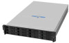
Hardware Installations and Upgrades All modules and/or blanking plates must be in place for the air to flow correctly around the storage system and to complete the internal circuitry. Before beginning your storage system installation, review the configuration requirements listed in Table 3 for the Intel® Storage System SSR212CC. Table 3. Configuration Requirements Module Location Drive Bays Power Supply Modules To ensure proper airflow, ALL drive bays must be fitted with either a drive carrier or a blank drive carrier. No bays should be left completely empty. A minimum of one drive should be installed. One power supply module must be installed in the power supply enclosure. Full power redundancy is available by installing a second power supply module. Drive Bay Numbering Convention The drive bay numbering convention is shown in the following figure. 1 2 3 4 5 6 7 8 9 10 11 12 TP01831 Figure 11. Drive Bay Numbering A bay is defined as the space required to house a single 1.0-in high 3.5-in disk drive in its carrier module, e.g., a 1 x 4 bay bank would take the space of one drive width by four drive bays across (in the rack mount configuration). The Intel® Storage System SSR212CC subsystem is housed in a 4 x 3 enclosure, i.e., four drive bays wide by three bays high. The top bays are numbered 1 to 4 from left to right, as viewed from the front. Drive carrier module locations are identified from a matrix of the top and side numbers. Additional drives must be populated in order from left to right, top to bottom, beginning with Drive Bay 1 and ending with Drive Bay 12. Warning: Operation of the enclosure with ANY modules missing will disrupt the airflow and the drives will not receive sufficient cooling. It is ESSENTIAL that all apertures are filled before operating the unit. Dummy drive carrier modules are available for fitting in unused drive bays. 12 Intel® Storage System SSR212CC User Guide
-
 1
1 -
2
-
3
-
4
-
5
-
6
-
7
-
8
-
9
-
10
-
11
-
12
-
13
-
14
-
15
-
16
-
17
-
18
-
19
-
20
-
21
-
22
-
23
-
24
-
 25
25 -
 26
26 -
 27
27 -
 28
28 -
 29
29 -
 30
30 -
 31
31 -
 32
32 -
 33
33 -
 34
34 -
 35
35 -
36
-
37
-
38
-
39
-
40
-
41
-
42
-
43
-
44
-
45
-
46
-
47
-
48
-
49
-
50
-
51
-
52
-
53
-
54
-
55
-
56
-
57
-
58
-
59
-
60
-
61
-
62
-
63
-
64
-
65
-
66
-
67
-
68
-
69
-
70
-
71
-
72
-
73
-
74
-
75
-
76
-
77
-
78
-
79
-
80
-
81
-
82
-
83
-
84
-
85
-
86
-
87
-
88
-
89
-
90
-
91
-
92
-
93
-
94
-
95
-
96
-
97
-
98
-
99
-
100
-
101
-
102
-
103
-
104
-
105
-
106
-
107
-
108
-
109
-
110
-
111
-
112
-
113
-
114
-
115
-
116
-
117
-
118
-
119
-
120
-
121
-
122
-
123
-
124
-
125
-
126
-
127
-
128
-
129
-
130
-
131
-
132
-
133
-
134
-
135
-
136
-
137
-
138
-
139
-
140
-
141
-
142
-
143
-
144
-
145
-
146
-
147
-
148
-
149
-
150
-
151
-
152
-
153
-
154
-
155
-
156
-
157
-
158
-
159
-
160
-
161
-
162
-
163
-
164
-
165
-
166
-
167
-
168
-
169
-
170
-
171
-
172
-
173
-
174
-
175
-
176
-
177
-
178
-
179
-
180
-
181
-
182
-
183
-
184
-
185
-
186
-
187
-
188
-
189
-
190
-
191
-
192
-
193
-
194
-
195
-
196
-
197
-
198
-
199
-
200
-
201
-
202
 |
 |
