Invacare BAR600IVC Owners Manual - Page 31
Tie Wrap
 |
View all Invacare BAR600IVC manuals
Add to My Manuals
Save this manual to your list of manuals |
Page 31 highlights
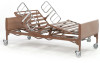
8 PACKAGING, HANDLING AND SET-UP Tie Wrap Tie Wrap FIGURE 3 Remove Tie Wraps 4. Align the inside of the head section with the inside of the foot section. Locking pins are located on the foot section frame and will make an audible click when properly engaged with the head section frame. 5. Push the head section towards the foot section so that the head section frame slides into the foot section frame and the locking pins engage. 6. Ensure the locking pins are properly engaged by attempting to pull the head section from the foot section. If the sections separate, repeat STEP 5-6 until the locking pins are secure. 7. Install the bed ends. Refer to Installing/Removing Bed Ends on page 34. 8. Connect the crossover cable. Refer to Connecting Crossover Cable on page 37. 9. Assemble and install the drive shaft. Refer to Assembling/Installing/Removing Drive Shaft on page 40. 10. Activate the bed functions. Refer to Inspecting the Bed on page 44. Part No 1123842 31 Invacare®IVC™Model BAR600IVC Bariatric Bed
-
 1
1 -
2
-
3
-
4
-
5
-
6
-
7
-
8
-
9
-
10
-
11
-
12
-
13
-
14
-
15
-
16
-
17
-
18
-
19
-
20
-
21
-
22
-
23
-
24
-
25
-
 26
26 -
 27
27 -
 28
28 -
 29
29 -
 30
30 -
 31
31 -
 32
32 -
 33
33 -
 34
34 -
 35
35 -
 36
36 -
37
-
38
-
39
-
40
-
41
-
42
-
43
-
44
-
45
-
46
-
47
-
48
-
49
-
50
-
51
-
52
 |
 |
