Invacare TRSX52FBP User Manual - Page 35
Adjusting Footplate Height, Spring Button,
 |
View all Invacare TRSX52FBP manuals
Add to My Manuals
Save this manual to your list of manuals |
Page 35 highlights
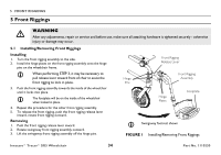
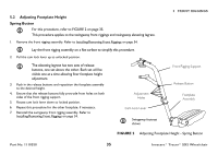
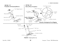
5.2 Adjusting Footplate Height Spring Button For this procedure, refer to FIGURE 2 on page 35. This procedure applies to the swingaway front riggings and swingaway elevating legrest. 1. Remove the front rigging assembly. Refer to Installing/Removing Front Riggings on page 34. Lay the front rigging assembly on a flat surface to simplify this procedure. 2. Pull the cam lock lever up to unlocked position. The elevating legrest has two sets of release buttons, one set above the other. Each set will be visible one at a time allowing finer footplate height adjustment. 3. Push in the release buttons and reposition the footplate assembly to the desired height. 4. Ensure that the release buttons fully protrude from holes on both sides of the front rigging support. 5. Rotate cam lock lever down to locked position. 6. Repeat this procedure for the other footplate, if necessary. 7. Reinstall the swingaway front rigging assembly. Refer to Installing/Removing Front Riggings on page 34. Adjustment Holes Cam Lock Lever Swingaway footrest shown 5 FRONT RIGGINGS Front Rigging Support Release Button Footplate Assembly FIGURE 2 Adjusting Footplate Height - Spring Button Part No. 1110550 35 Invacare® Tracer® SX5 Wheelchair
-
 1
1 -
2
-
3
-
4
-
5
-
6
-
7
-
8
-
9
-
10
-
11
-
12
-
13
-
14
-
15
-
16
-
17
-
18
-
19
-
20
-
21
-
22
-
23
-
24
-
25
-
26
-
27
-
28
-
29
-
 30
30 -
 31
31 -
 32
32 -
 33
33 -
 34
34 -
 35
35 -
 36
36 -
 37
37 -
 38
38 -
 39
39 -
 40
40 -
41
-
42
-
43
-
44
-
45
-
46
-
47
-
48
-
49
-
50
-
51
-
52
-
53
-
54
-
55
-
56
-
57
-
58
-
59
-
60
-
61
-
62
-
63
-
64
-
65
-
66
-
67
-
68
-
69
-
70
-
71
-
72
-
73
-
74
-
75
-
76
-
77
-
78
-
79
-
80
-
81
-
82
-
83
-
84
 |
 |
