Invacare TRSX52FBP User Manual - Page 38
Replacing Heel Loop
 |
View all Invacare TRSX52FBP manuals
Add to My Manuals
Save this manual to your list of manuals |
Page 38 highlights
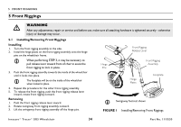
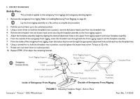
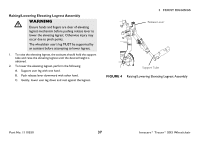
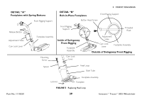
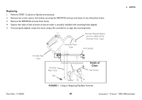
5 FRONT RIGGINGS 5.3 Replacing Heel Loop For this procedure, refer to FIGURE 5 on page 39. 1. Pull the cam lock lever up to unlocked position. 2. Perform one of the following: • Footplates with Spring Buttons (Detail "A"): i. Push in the release buttons and remove the footplate assembly from the front rigging support. • Bolt-In-Place Footplates (Detail "B"): i. Using a screw driver to hold the threaded rivet in position, remove the button head screw from the threaded rivet. ii. Remove the threaded rivet and button head screw securing the footplate assembly to the front rigging support. 3. Remove the mounting screw, spacer and locknut that secure the heel loop to the footplate. 4. Remove existing heel loop from slide tube. 5. Install new heel loop onto slide tube. 6. Install the mounting screw, spacer and locknut to secure the heel loop to the footplate. Tighten until the spacer is secure. 7. Insert the lower footrest assembly into the upper footrest assembly to desired height. 8. Perform one of the following: • Footplates With Spring Buttons (Detail "A"): i. Ensure that the release buttons fully protrude from holes on both sides of the upper footrest support. • Bolt-In-Place Footplates (Detail "B"): i. From the outside of the swingaway front rigging, insert the threaded rivet through both the front rigging support and the footplate assembly. ii. From the inside of the swingaway front rigging, insert the button head screw through the appropriate adjustment hole and thread into the threaded rivet. iii. Using a screwdriver to hold the threaded rivet in position, securely tighten the button head screw. Torque to 32 in-lbs. 9. Rotate cam lock lever down to locked position. Invacare® Tracer® SX5 Wheelchair 38 Part No. 1110550
-
 1
1 -
2
-
3
-
4
-
5
-
6
-
7
-
8
-
9
-
10
-
11
-
12
-
13
-
14
-
15
-
16
-
17
-
18
-
19
-
20
-
21
-
22
-
23
-
24
-
25
-
26
-
27
-
28
-
29
-
30
-
31
-
32
-
 33
33 -
 34
34 -
 35
35 -
 36
36 -
 37
37 -
 38
38 -
 39
39 -
 40
40 -
 41
41 -
 42
42 -
 43
43 -
44
-
45
-
46
-
47
-
48
-
49
-
50
-
51
-
52
-
53
-
54
-
55
-
56
-
57
-
58
-
59
-
60
-
61
-
62
-
63
-
64
-
65
-
66
-
67
-
68
-
69
-
70
-
71
-
72
-
73
-
74
-
75
-
76
-
77
-
78
-
79
-
80
-
81
-
82
-
83
-
84
 |
 |